
Subscribe to Our Youtube Channel
Related Manuals for System Q PTZ922


Summary of Contents for System Q PTZ922
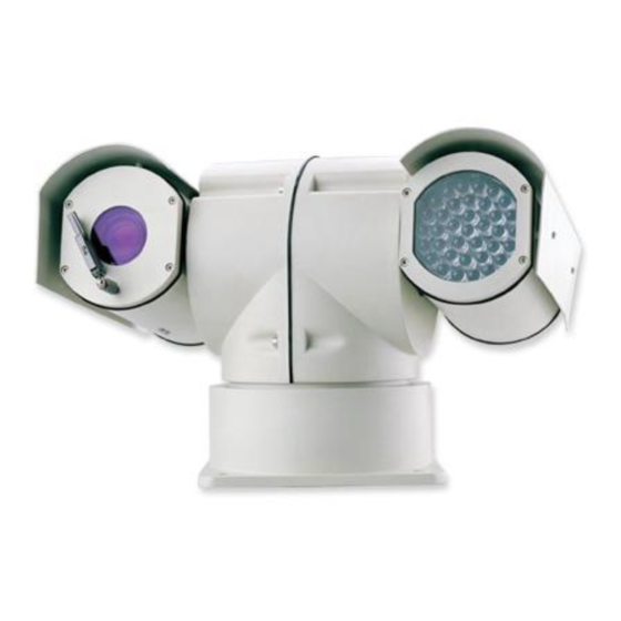
- Page 1 Armoured range www.excelptz.com Installation and Operation Manual PTZ922 HIGH Speed Armoured Pan Tilt Zoom 24V AC model with Infrared Camera & Wiper Models Covered PTZ922J 22x Zoom PTZ922P 30x Zoom Version 1.0...
-
Page 2: Table Of Contents
Overcoming RS485 data loss using an RS485 distributor Setting up the PTZ Camera RS485 connection – Connecting the Keypad or DVR to the PTZ922 Connecting the video out of the PTZ If you are using more than one PTZ on a site... -
Page 3: Safety Precautions
1. Please read the operation manual carefully before installing and operating the product. 2. The PTZ922 requires a 24v AC power supply. The rated input voltage of the camera in the PTZ is 12V!!!! This gets its power from the PTZ922 and does not require a separate PSU. Do not connect 24V AC to the camera under any circumstances!! 3. -
Page 4: Key Functions
It has a panoramic variable speed PAN/TILT movement, a multifunctional decoder, a character generator and an on-board processor for logic handling. The PTZ922 is easy to connect, install, maintain and operate, and has many special features. Its unique design and shape offers a more obvious deterrent with its infrared capability and robust construction. -
Page 5: Special Ptz Features - 4 Channel Alarm Input Activation & Channel Alarm Output
c. Backlight Compensation: When the object to be shot has a dark background, the user can increase the backlight compensation accordingly. d. White Balance: If the image has incorrect colours displayed on the monitor, the user can use different modes to alter the white balance. There are 6 modes for selection: Indoor Mode, Outdoor Mode, Trigger Mode, Auto tracking White Balance, Manual White Balance and Automatic Mode. - Page 6 Wiper Control The PTZ922 incorporates a wiper facility to clean the front glass cover. Note that the wiper is not a windscreen wiper as used in a car. The purpose of the wiper is to clear away dust on a periodic basis from the front glass lens cover without having to have physical access to the PTZ.
-
Page 7: Getting The Ptz Up & Running
Generally speaking, PTZs require four things; 1- They require a power supply and a cable to supply this power to the PTZ. The PTZ922 operates on 24V A.C like many external PTZ domes but some mini pan and tilt domes are 12V. - Page 8 Equipment Cable Needed 1. Data signal CAT5 cable Keypad or You can also send the video signal back along a second pair in a CAT5 cable using baluns. Note you cannot send 24v AC power down CAT5. 2. Video signal RG59 or similar You can combine both the video and power into one cable if you...
-
Page 9: Rs485 Wiring Methods & Tips
CAT 5 CCT CAMERA 24 V AC CAT5 Carries Video & LOCAL Control Data 240V --- Video & Power RG59+2 Video & Power BALUN TRADITIONAL CAT5 Carrying Data CAMERA 240V JUNCTION BOX Free Lead Supplied CO-AX RG59 KEYPAD MONITOR Many installation companies can get the power and video signal correct, but struggle with the control of the PTZ using the keypad or DVR using the RS485 data. - Page 10 PLEASE NOTE - Using inferior cables, or installing the PTZ in an environment with strong electromagnetic interference, or connecting a lot of PTZ domes to the same cable carrying the RS485 signal will reduce the maximum transmitting distance. 3. RS485 Connection methods METHOD 1 –DAISY CHAIN CONNECTION.
- Page 11 JP1 IS THE 120 TERMINATION & JP2 IS THE EXTERNAL SYNCHRONISATION ON THIS PTZ922 24V AC PTZ, THE JP2 JUMPER MUST BE SET TO EXT SYNC OFF The JP2 jumper is the connection terminal for the external synchronisation of the PTZ which...
-
Page 12: Overcoming Rs485 Data Loss Using An Rs485 Distributor
STAR method of connection. In some circumstances you may need to adopt a star configuration for practical purposes. For instance, all the PTZs may be so scattered on a large site that running out separate spurs to each PTZ in a “ STAR” array is the only practical solution. - Page 13 are in effect correcting the STAR method of RS485 data distribution. As previously mentioned the problem with the Star method is that it is not actually designed for RS485 but generally works okay if you follow the previous notes on getting the 120 resistor setting right, as per the previous notes.
-
Page 14: Setting Up The Ptz Camera
Setting up the PTZ Camera 1. Connection of the System There are many ways to wire up a PTZ system. If you have read the introduction at the beginning of these instructions you should have got a good idea what your options are. -
Page 15: Rs485 Connection - Connecting The Keypad Or Dvr To The Ptz922
Powering the PTZs- All the PTZs will need power. For this PTZ it is a 24V A.C power supply. The power supply must be capable of delivering at least 1.25A per PTZ. You can either power each PTZ with its own PSU locally to it or have the PSU’ s remotely situated perhaps near the keyboard or DVR. - Page 16 The PTZ730 and PTZ700 are two keypads that can be used PTZ730 keypad with the PTZ922 range. On the rear of the keypads you will see the RS485 connections. Ensure they are connected correctly i.e the RS485 + A line and the RS485 – B line.
-
Page 17: Connecting The Video Out Of The Ptz
Connecting the video out of the PTZ. The PTZ922 has a short BNC lead attached to it, this is the lead that carries the video signal from the built-in camera. You need to extend this lead to the “ VIDEO-IN” of the DVR or monitor. Use a good quality RG59 coax cable or similar to do this. - Page 18 24V AC INPUT RS485 RS485 - ‘ B’ YELLOW + ‘ A’ ORANGE RS485 COMBINER RS485 Data Cable RS485 INPUT ON DVR 24 VAC...
-
Page 19: If You Are Using More Than One Ptz On A Site
SW2 sets up the protocol. This switch is dealt with later in these instructions. For most System Q equipment they should always be set to PELCO-D 2400 baud rate. In the diagram this is correct. The Jumper on the far right either enables or disables the 120 resistor. -
Page 20: Setup Of The Protocol And The Default Baud Rate
As shown in Table 2, SW2 is used to set the protocol and the baud rate used by the PTZ camera. DIP-4 to DIP-1 of SW2 is used to select protocols and a maximum of 16 different protocols can be selected. Pelco-D 2400 is used for most System Q equipment. DIP status... - Page 21 Setup of the Baud Rate. As shown in Figure 2, SW2 is used to set the protocol of communication and the baud rate used by the PTZ922 camera. DIP-6 and DIP-5 of SW2 are used to select the baud rate and 4 different baud rates can be selected. If the controller adopts a non-standard baud rate, you can adjust it to be identical with that of the controller, as per the following table.
-
Page 22: Using The Ptz730 Keypad With The Ptz922
Using the PTZ730 keypad with the excelPTZ series NOTE 1: For more detailed instructions in setting up the keypad or using one of our other keypads, please refer to the instruction manual supplied with the product. NOTE 2: The PTZ730 keypad requires you to press the function key first followed by the value e.g <CAM>... -
Page 23: Presets And Other Functions
PRESETS and other functions. The PTZ922 has up to 128 presets that once programmed will stay in the PTZ’ s non-volatile memory so they will be retained even after a power cut. What is a preset? A preset is a particular area or object that the PTZ was looking at and has been stored into its memory so when the preset is “... -
Page 24: Patrols (Tours) - How To Set Them Up And Use Them
Patrols (Tours) – How to set them up and use them A patrol (tour) is simply a collection of at least three preset camera locations that are run in sequence with the PTZ stopping at each location for a brief period of time and then moving on to the next preset. For example, you could use a patrol so that an outside PTZ camera points at a gate, then at a side doorway, then zooms out to get an overall shot of a car park and finally zooming in on a delivery bay, before repeating the whole cycle again. - Page 25 Setting the Patrol (Tour) To setup the patrol/tour you need to enter the Advanced Menu System by selecting CALL 95 Enter on the keypad. You will see the Main Menu displayed on the screen. Using the joystick up/down direction movement, select the PROGRAM menu. Use the joystick pan right movement to enter this menu.
- Page 26 Now exit the menu by moving the Joystick down, selecting EXIT and then moving the Joystick to the right to return to the Main Menu. Again use the Joystick to select EXIT and exit the Advanced Menu System by selecting the right pan movement. Calling the Patrol (Tour) There are two methods of initiating the patrol or tour.
-
Page 27: Auto Scan - How To Set It Up - Calling The Auto Scan
AUTO SCAN- How to set it up Auto-scan scans between two points. These are not presets as per the patrol (tour) facility but auto scan selection points. You may program only one auto scan. STEP 1 – Select the required camera by entering <camera address> and pressing the CAM button on the keypad. -
Page 28: Record Pattern- What Is A Record Pattern
99 seconds at each of sixteen preset positions. In addition up to six different patrols (tours) can be stored each with different preset parameters whereas only one record pattern can be recorded. When a preset is stored the PTZ922 stores not only the preset position but also the camera attributes. - Page 29 Using the joystick up/down direction movement, select the PROGRAM menu. Use the joystick pan right movement to enter this menu. In the PROGRAM menu select RECORD PATTERN followed by pressing CLOSE button to save. STEP 2 – Now move the camera using the keypad joystick to record a forty second sequence and follow this by pressing the CLOSE button to save.
-
Page 30: Using The Ptz' S Advanced Functions
USING THE PTZ922’ S ADVANCED FUNCTIONS- On Screen Graphics (OSD) – The PTZ922 boasts six patrol (tour) options, an auto scan option and a record pattern option. All these can be configured using the OSD. To bring up the camera menu press CALL 95 Enter. The OSD is then displayed on the screen. You can navigate between the various options using the Joystick control –... -
Page 31: Using The Advanced Menu System
Set auto pan start & end – run auto pan – edit preset title – setup patrols/tours – run patrols /tours – record pattern – run pattern. PAL CAMERA: To switch between PAL and NTSC camera mode. CAM DEFAULT SET: To select camera default settings. RESET PT: To reset the PTZ922. EXIT: To exit menu. -
Page 32: Display Setup
DISPLAY SETUP To access Display Setup press the OPEN button on keypad or move the Joystick to the right. The menu below will be displayed. MAIN MENU DISPLAY SETUP 1. DISPLAY SETUP ID DISPLAY 2. CAMERA SETUP ID POS TOP-L 3. - Page 33 CAM DISPLAY ON / OFF When this is set to ON the camera screen will be opened. To toggle the settings move the Joystick to the right or press the OPEN button. To return to Main Menu use the Joystick down movement to RETURN and press the OPEN button on the keypad or move the Joystick to the right.
-
Page 34: Camera Setup
CAMERA SETUP Move the Joystick down to select Camera Setup and press the OPEN button or move the Joystick to the right. The menu below will be displayed. CAMERA SETUP MAIN MENU 1. DISPLAY SETUP SLOWSHUTTER AUTO 2. CAMERA SETUP BACK LIGHT 3. - Page 35 D-ZOOM ON / OFF Setup of digital zooming. This allows the digital zoom function to be switched on or off. To toggle the settings move the Joystick to the right or press the OPEN button. To return to Main Menu use the Joystick down movement to RETURN and press the OPEN button on the keypad or move the Joystick to the right.
-
Page 36: Control Setup
CONTROL SETUP Move the Joystick down to select Control Setup and press the OPEN button or move the Joystick to the right. The menu below will be displayed. MAIN MENU CONTROL SETUP 1. DISPLAY SETUP 2. CAMERA SETUP ALARM 3. CONTROL SETUP HOME OPTION 4. - Page 37 IR LED OFF/ON The default option of the Infrared Lamp is OFF. Normally the PTZ922 detects external illumination and opens and closes the infrared lamp automatically. If the user changes this option to ON, the operation of the Infrared becomes a manual operation.
-
Page 38: Camera Mask Set
CAMERA MASK SET Move the Joystick down to select Program and press the OPEN button or move the Joystick to the right. The menu below will be displayed. MAIN MENU CAMERA MASK SET DISPLAY SETUP CAMERA SETUP MASK PRIVACY MASK SHADE BLACK CONTROL SETUP CAMERA MASK SET... -
Page 39: Program
PROGRAM Move the Joystick down to select Program and press the OPEN button or move the Joystick to the right. The menu below will be displayed. MAIN MENU PROGRAM 1. DISPLAY SETUP AUTO PAN START POS 2. CAMERA SETUP AUTO PAN END POS RUN AUTO PAN SLOW 3. - Page 40 0-9, A-Z, +, - and space. NOTE: The first character of the title must be 0-9 or A-Z. SET PATROL To edit data for a patrol/tour. Select sequence number of patrol by using the Joystick pan left or pan right, press OPEN button to select edit mode and edit using the up/down Joystick movement, setting the POS (preset number), the Joystick pan right to select the PTZ speed (SP) and the dwell time (TM) followed by the CLOSE button to save and exit.
-
Page 41: Pal/Ntsc Camera
PAL CAMERA No sub-menu option for this. MAIN MENU 1. DISPLAY SETUP 2. CAMERA SETUP 3. CONTROL SETUP 4. CAMERA MASK SET 5. PROGRAM 6. PAL CAMERA 7. CAM DEFAULT SET 8. RESET PT 9. EXIT PAL / NTSC CAMERA To switch from PAL to NTSC camera use the Joystick pan left or pan right. -
Page 42: Cam Default Set
CAM DEFAULT SET No sub-menu option for this. MAIN MENU 1. DISPLAY SETUP 2. CAMERA SETUP 3. CONTROL SETUP 4. CAMERA MASK SET 5. PROGRAM 6. PAL CAMERA 7. CAM DEFAULT SET 8. RESET PT 9. EXIT CAM DEFAULT SET This option sets the camera default settings. -
Page 43: Reset Pt
6. PAL CAMERA 7. CAM DEFAULT SET 8. RESET PT 9. EXIT RESET PT This option resets the PTZ922 settings. The following display will be output OPERATION WILL Use the Joystick left or right pan to toggle between YES CLEAR ALL TITLES and NO. -
Page 44: Exit
1. In the PTZ922 the address 1 is set as default in the factory. You need to alter the DIP-switches within the PTZs to address 2, 3 etc if you have multiple PTZs on the same site, refer to the previous instructions how to set the DIP Switches. -
Page 45: Installation Instructions
Installation Instructions Product Dimensions Outline Sizes of the PTZ922 Side Elevation End Elevation... -
Page 46: Installation Steps
4. Connect the output wires of the socket according to relative colours on the schematic drawing. Ensure that the correct cables are used. Attention: refer to power label 5. On the PTZ922 the 10-core socket is used as the alarm interface and detailed connection can be seen from the description of colours of terminals. -
Page 47: 7. 4 Channel Alarm Input Activation & Single Channel Alarm Output
6. 7 & 10 Core Terminal connections 7 CORE TERMINAL 10 CORE TERMINAL FOR ALARMS PIN 1 24V AC RED 1. Alarm-1 in: red PIN 2 24V AC BLACK 2. Alarm-2 in: orange PIN 3 RS485 - YELLOW 3. Alarm-3 in: yellow PIN 4 NOT USED PIN 5 RS485 + ORANGE 4. - Page 48 1. Alarm-1 in: red 2. Alarm-2 in: orange 3. Alarm-3 in: yellow 4. Alarm-4 in: green 5. NC 6. Alarm in COM: black 7. Alarm Out COM: black 10-Core Input Terminal 8. NC 9. Alarm NO out: blue 10.Alarm NC COM: pink 8) Connecting the Input Alarm devices Refer to above 10 core input terminal.
- Page 49 when Alarm Channel No 3 is activated it calls preset number 31 when Alarm Channel No 4 is activated it calls preset number 32 To set these special presets, if you have set up alarm channel 1, move the PTZ camera to where you wish alarm 1 preset to move to, and using the keypad press 29 followed by the Preset button.
- Page 50 13) Connecting the Output Alarm In addition to the alarm inputs, the PTZ900 will activate an alarm output if an alarm input is triggered. There are two connections for the alarm output, a common and either a normally open or a normally closed connection. Again this is a 0 volt switch and could be used for example to close a circuit to an audible alarm, lighting or other warning devices.
-
Page 51: Vi. Technical Data Table
VI. Technical data table Image Inductor Depends on camera type fitted Pixels Depends on camera type fitted In-Phase System In-Phase Inside Video Output 1.0 Vp-p/75 White Balance Auto / Manual Power Supply AC 24V±10% 1.75A Power Consumption 42 VA Specifications Weight 10Kg Operating Temperature... -
Page 52: Appendix A: Lightning Proof And Surge Signal Proof
Appendix A: Lightning Proof and Surge Signal Proof This product adopts TVS lightning proof technology to prevent damage by a lightning strike below 1500 W and surge impulse signals. However it is also necessary to ensure that the following precautions are taken to ensure electrical safety: Keep the communication cables at least 50 meters away from high voltage equipment or cables.
Need help?
Do you have a question about the PTZ922 and is the answer not in the manual?
Questions and answers