
Subscribe to Our Youtube Channel
Related Manuals for System Q PTZ280


Summary of Contents for System Q PTZ280
- Page 1 Mini Hi-Speed Dome Installation and Operation Manual PTZ280 For Internal or External Use 12vDC Run Tours Autoscans Patterns Plus On Screen Menu Version 1.0...
-
Page 2: Table Of Contents
CONTENTS TABLE Description Page No. Contents Safety Precautions Description of Functions Integrated Multi-Protocol Decoder Integrated Speed – Variable PAN/TILT High Intelligent Settings Modify Dome Address by RS485 Setting Protocol and Baud Rate Getting the dome up & running Overview – introduction to fitting PTZ equipment RS485 Wiring methods &... - Page 3 Motion Setup Presets Auto Scan Patrols Patterns Clear Privacy Mask Advance Setup Home Setup Password CAM ID Setup Fan Control Language Set North Position System Reset Controlling one camera then another System Installation Technical Specification Appendix A: General Information Troubleshooting...
- Page 4 Please read this operation manual carefully before installing and using this unit !!!! Please read the following; 1. Please read the operation manual carefully before installing and operating the product. 2. The actual dome requires a 12v DC regulated power supply. The rated input voltage of the camera is 12V.
-
Page 5: Description Of Functions
Description of Functions This intelligent dome camera is a hi-tech CCTV product, which incorporates a high- clarity colour camera. It has a panoramic variable speed PAN/TILT movement, a multifunctional decoder, a character generator and an on-board processor for logic handling. The dome is easy to connect, install, maintain and operate, and has many features. -
Page 6: Getting The Dome Up & Running
g. Angle Display. Three options for displaying camera angle settings. h. Software Modify the Dome Address. Allows dome address to be changed through RS485 software (ID Change in Advance Settings) i. Returns to last position. If unit loses power, when re-powered it can be set to return after the self test to the position that it was at, when power was lost. -
Page 7: Overview- Introduction To Fitting Ptz Equipment
Overview- introduction to fitting PTZ equipment Generally speaking, PTZ Domes requires four things; 1- They require a power supply and a cable to supply this power to the dome. Often, external domes are 24V A.C but this mini pan is 12V DC. 2- They require a cable to get the video signal back to the monitor or recording device. - Page 8 installation companies use a CAT5 type or similar cable to run out to the domes to carry the data signal. If you are considering using baluns please note - DVR’ s tend to require very good video signals to function correctly and “ passive baluns” can loose some signal strength over the 50 metre mark so try to restrict the use of passive baluns to below 50 metre cable runs when using them with DVRs.
-
Page 9: Rs485 Wiring Methods & Tips
RS485 Wiring methods & Tips >>>>> 1. Characteristics of RS485 As specified by RS485 standards, RS485 is a half-duplex data transmission type with characteristic impedance of 120 . The maximum load capacity is 32 units (domes, keyboards and DVRs). 2. Transmission distances of RS485 Signals using CAT5 or similar cables Selecting a CAT5 or similar sized twisted pair data transmission cable, the maximum theoretical transmitting distances are as follows: Baud Rate... -
Page 10: Star Method Of Connection
(just the last dome only has the 120 resistor set to on, the first device is the keyboard and has the 120 built in as default) This next diagram is a slight variation on the Daisy Chain arrangement. Again it’ s one cable going out to all the domes but instead of the cable going into each dome then back out to the next one, a junction box is used to “... -
Page 11: Overcoming Rs485 Data Loss Using An Rs485 Distributor
The termination resistors must be connected to the two domes that are farthest away from each other, such as domes 3 and 5 in the following “ Star diagram” . Note that all the other domes do not have the 120ohm resistor connected. The resistors are already fitted to the domes PCB but by default are not in circuit. - Page 12 Although the RS485 distributor is a small additional expense, it takes some of the guess work out of the installation design and gives a more flexible approach to cabling which itself can save time and money on the installation. Not forgetting you get more predictable results! The RS485 distributor (PTZ750) amplifies the RS485 control signal and distributes it evenly to 4 separate spurs, each spur can have up to 4 domes.
-
Page 13: Setting Up The Dome Camera
Setting up the Dome Camera 1. Connection of the System There are many ways to wire up a PTZ system. If you have read the introduction at the beginning of these instructions you should have got a good idea what your options are. Below is a general schematic diagram showing you some of these options. -
Page 14: Rs485 Connection - Connecting The Keypad Or Dvr To The Dome
Please note - The domes heater doesn’ t come on until it senses the temperature drops below 0 degrees Celsius. Please make sure that you have a sufficient power supply and cable installed to cope with this. Obviously the dome may work okay in the summer but when winter kicks in and the dome’... - Page 15 CAT5 or similar cable. Note that data cables do not need to be connected through baluns. The PTZ730 and PTZ700 are two keypads that can be used with the PTZ280 series. On the rear of the keypads you will see the RS485 connections. Ensure PTZ730 they are connected correctly i.e the RS485 + A line...
-
Page 16: Connecting The Video Out Of The Dome
If you use cores from two different pairs in the CAT5 cable you will not get the benefit of the shielding effect of the cable twists and the dome will function erratically. You must always use a core from a PAIR, not two cores from two different pairs!! Connecting the video out of the dome. - Page 17 12V DC INPUT RS485 RS485 - ‘ B’ + ‘ A’ YELLOW ORANGE RS485 INPUT ON 12vDC...
-
Page 18: If You Are Using More Than One Dome On A Site
If you’ re using more than one dome on a site Each dome has a unique “ address” so that if you are using more than one on a site the keyboard “ talks” to the right dome when you want it to PTZ. If you only have the one dome on the site then the default “... -
Page 19: Entering The Address In The Menu
Entering the address in the menu To enter the main menu CALL preset 64 or CALL preset 95 or CALL preset 1 twice within 4 seconds using the keypad or DVR with PTZ control. Enter the ADVANCE SETTING menu and select ID CHANGE. Check the CAMERA S/N: and enter this in INPUT S/N: then enter the NEW ID: and enter the new ID from 001 –... -
Page 20: Using The Ptz730 Keypad With The Excelptz Series
Using the PTZ730 keypad with the excelPTZ series NOTE 1: For more detailed instructions in setting up the keypad or using one of our other keypads, please refer to the instruction manual supplied with the product. NOTE 2: The PTZ730 keypad requires you to press the function key first followed by the value e.g <CAM>... -
Page 21: Presets And Other Functions
PRESETS and other functions. The dome has up to 128 presets that once programmed with stay in the domes non-volatile memory so they will be retained even after a power cut. What is a preset? A preset is a particular area or object that the dome was looking at and has been stored into its memory so when the preset is “... -
Page 22: Deleting A Preset
For example, you could use a patrol so that an outside dome camera points at a gate, then at a side doorway, then zooms out to get an overall shot of a car park and finally zooming in on a delivery bay, before repeating the whole cycle again. -
Page 23: Calling The Patrol (Tour)
POS TM POS TM To edit a patrol sequence Patrol Item No. No. of Preset Position Dwell time at this position Time 0 ~ 99 seconds SEQ:nn The Patrol number. (01 ~ 06) PATROL:01 CLOSE:EXIT Special Note: The patrol item number (NO) is an ascending number list of the preset items within this sequence. -
Page 24: Auto Scan- How To Set It Up
Special Note: If you notice that some expected presets are not being incorporated in a patrol/tour, check that the PATROL table has been setup correctly and shows all presets for the required sequence. A full explanation of the values to be set can be found in the previous section Setting the Patrol (Tour). -
Page 25: Record Pattern- What Is A Record Pattern
Using the joystick up/down direction movement, select the MOTION SETUP menu. Use the joystick pan right movement to enter this menu. In the AUTO SCAN menu select RUN SCAN. If the start position is the same as the end position it will do a 360° scan. Now press the CLOSE button to save and initiate the Auto Scan. -
Page 26: Running The Record Pattern
STEP 1 – Select the required camera by pressing the CAM button and entering <camera address> followed by <Enter> on the keypad. Position the camera where you wish to start the record pattern sequence. Enter the Main Menu System by selecting <CALL> 95 <Enter> or <CALL> 64 <Enter> on the keypad. - Page 27 USING THE DOME’ S ADVANCED FUNCTIONS- On Screen Graphics (OSD) – The PTZ605 series boasts six patrol (tour) options, an auto scan option and a record pattern option. All these can be configured using the OSD. or <CALL> 64 <Enter> To bring up the camera menu press <CALL>...
-
Page 28: System Setup
THE MENU SYSTEM Using the Menu System. This menu system allows the user to alter the dome menu instruction options and settings using a control keypad. This first page shows the initial main menu page and only describes the general functions. - Page 29 To access System Setup press the OPEN button on keypad or move the Joystick to the right. The menu below will be displayed. MAIN MENU SYSTEM SETUP 1. SYSTEM SETUP 1. SYSTEM INFORMATION 2. DISPLAY SETUP 2. AUTO FLIP 3. CAMERA SETUP 3.
- Page 30 Move the Joystick down to select Display Setup and press the OPEN button or move the Joystick to the right. The menu below will be displayed. MAIN MENU DISPLAY SETUP 1. SYSTEM SETUP 2. DISPLAY SETUP 1. <CAMERA ID> <see 1 below> 2.
- Page 31 Move the Joystick down to select Camera Setup and press the OPEN button or move the Joystick to the right. The menu below will be displayed. MAIN MENU CAMERA SETUP 1. SYSTEM SETUP 1. D-ZOOM 2. DISPLAY SETUP 2. DISPLAY 3.
- Page 32 1. AE MODE Automatic Exposure AUTO / MANU / SHUTTER Normally set to AUTO. SHUTTER Only available if AE MODE is set to SHUTTER Select from 1/50, 1/100, 1/250, 1/500, 1/700, 1/1000, 1/1600, 1/2500, 1/5000. 2. WB MODE ATW / MANUAL This option is set to ATW.
- Page 33 Move the Joystick down to select Motion Setup and press the OPEN button or move the Joystick to the right. The menu below will be displayed. MAIN MENU MOTION SETUP 1. SYSTEM SETUP 1. <PRESETS> 2. DISPLAY SETUP 2. <AUTO SCAN> 3.
- Page 34 5. RUN SCAN To run a scan first set the start and end position. Note that if the start and end position are the same the dome will scan 360 degrees. Press CLOSE to exit. 6. CLEAR SCAN If you wish to clear the auto scan select this item and then press CLOSE to exit. PATROLS <PATROLS>...
- Page 35 <PATTERNS> PATTERNS 1. PATTERN NO. 1. PATTERN NO. Allows recording of a pattern for up to 200 seconds. 2. RECORD PATTERN Up to 3 patterns can be recorded. 3. RUN PATTERN 4. CLEAR PATTERN 2. RECORD PATTERN 5. RETURN Click on this menu item to start pattern recording and when complete press CLOSE to save.
- Page 36 Move the Joystick down to select Motion Setup and press the OPEN button or move the Joystick to the right. The menu below will be displayed. MAIN MENU PRIVACY MASK 1. SYSTEM SETUP 1. PRIVACY MASK 2. DISPLAY SETUP 2. MASK SHADE WHITE 3.
- Page 37 Move the Joystick down to select Motion Setup and press the OPEN button or move the Joystick to the right. The menu below will be displayed. MAIN MENU ADVANCE SETUP 1. SYSTEM SETUP 1. <HOME SETUP> 2. DISPLAY SETUP 2. <PASSWORD> 3.
- Page 38 ADVANCE SETUP MAIN MENU 1. SYSTEM SETUP 1. <HOME SETUP> 2. DISPLAY SETUP 2. <PASSWORD> 3. CAMERA SETUP 3. <CAM ID SETUP> 4. MOTION SETUP 4. <FAN CONTROL> 5. PRIVACY MASK 5. LANGUAGE: ENGLISH 6. ADVANCE SETUP 6. SET NORTH POSITION 7.
- Page 39 CAM ID SETUP CAM ID SETUP This enters the software ID settings menu 1. CAMERA S/N: 9999999 2. INPUT S/N: 0000000 1. CAMERA S/N: 3. OLD ID: Displays the dome series number 4. NEW ID 5. SAVE & RETURN 2. INPUT S/N: 6.
- Page 40 FAN CONTROL) FAN CONTROL To set the fan control menu settings. 1. FAN 1. FAN ON / OFF / AUTO 2. OPEN TEMP: The fan working conditions can be set. 3. TEMP DISPLAY ON Setting to ON will set fan running and OFF 4.
-
Page 41: Controlling One Camera Then Another
Controlling one camera then another. If you look at the image of the LCD display on the keypad you can see the CAM=001 indicates that the keyboard is ready to talk to camera with address 1. In the dome the address 1 is set as default in the factory. -
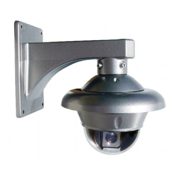
Page 42: System Installation
System Installation Outdoor Wall Installation Unpack the carton and carefully remove the dome camera and attachments. Fit the flange on the outdoor sunshade with three M4 x 8 inner hexagon screws. Fit the flat bottom plate to the sunshade with three M3 x 6 pan head screws. Remove the dome and connect three fast fix screws into the flat plate of the dome and connect it to the sunshade by turning the dome clockwise to tighten it. -
Page 43: Technical Specification
Technical Specification Power Supply 12v DC 2A regulated power supply Synchronisation Internal Preset positions No. of Tours / Patrols Pattern record time 3 patterns for up to 120 seconds per pattern Privacy zone masking 4 areas that move when PTZ moves Zoom rotation interaction The dome will automatically adjust manual control speed... -
Page 44: Troubleshooting
Appendix A: General Information The Cleaning of Clear Dome Cover To obtain constant clear images, the user should clean the dome cover periodically. l Be very careful when cleaning. Hold the dome cover ring only to avoid touching the acrylic dome cover. The acid from fingerprints will corrode the coating and any scratches on the dome cover may cause distorted or poor images.
Need help?
Do you have a question about the PTZ280 and is the answer not in the manual?
Questions and answers