Table of Contents
Advertisement
Quick Links
OPERATOR MANUAL
KEPCO INC.
An ISO 9001 Company.
IMPORTANT NOTES:
1)
This manual is valid for the following Model and associated serial numbers:
MODEL
2)
A Change Page may be included at the end of the manual. All applicable changes and
revision number changes are documented with reference to the equipment serial num-
bers. Before using this Instruction Manual, check your equipment serial number to identify
your model. If in doubt, contact your nearest Kepco Representative, or the Kepco Docu-
mentation Office in New York, (718) 461-7000, requesting the correct revision for your
particular model and serial number.
3)
The contents of this manual are protected by copyright. Reproduction of any part can be
made only with the specific written permission of Kepco, Inc.
Data subject to change without notice.
©2013, KEPCO, INC,
P/N 243-1324b
KEPCO, INC. ! 131-38 SANFORD AVENUE ! FLUSHING, NY. 11355 U.S.A. ! TEL (718) 461-7000 ! FAX (718) 767-1102
ATE-DMG SERIES
POWER SUPPLY
MODELS
ATE 6-100DMG, ATE 15-50DMG,
ATE 25-40DMG, ATE 36-30DMG,
ATE 55-20DMG, ATE 75-15DMG,
ATE 100-10DMG, ATE 150-7DMG
ORDER NO.
SERIAL NO.
email: hq@kepcopower.com ! World Wide Web: http://www.kepcopower.com
REV. NO.
REV. NO.
KEPCO
THE POWER SUPPLIER™
®
Advertisement
Table of Contents

Subscribe to Our Youtube Channel
Related Manuals for KEPCO ATE 6-100DMG


Summary of Contents for KEPCO ATE 6-100DMG
-
Page 1: Power Supply
Data subject to change without notice. KEPCO ® ©2013, KEPCO, INC, P/N 243-1324b THE POWER SUPPLIER™ KEPCO, INC. ! 131-38 SANFORD AVENUE ! FLUSHING, NY. 11355 U.S.A. ! TEL (718) 461-7000 ! FAX (718) 767-1102 email: hq@kepcopower.com ! World Wide Web: http://www.kepcopower.com... -
Page 3: Declaration Of Conformity
93/68/EEC (CE mark) Standard to which Conformity is declared: EN61010-1:2001 (Safety requirements for electrical equipment for measurement, control and laboratory use - Part 1) KEPCO INC. Manufacturer's Name and Address: 131-38 SANFORD AVENUE FLUSHING, N.Y. 11355 USA Importer's Name and Address:... - Page 4 There are no user or operator serviceable parts within the product enclosure. Refer all servicing to qualified and trained Kepco service technicians. 228-1351 COND/CONFORM 020613...
-
Page 5: Safety Instructions
SAFETY INSTRUCTIONS 1. Installation, Operation and Service Precautions This product is designed for use in accordance with EN 61010-1 and UL 3101 for Installation Category 2, Pollution Degree 2. Hazardous voltages are present within this product during normal operation. The prod- uct should never be operated with the cover removed unless equivalent protection of the operator from accidental contact with hazardous internal voltages is provided: There are no operator serviceable parts or adjustments within the product enclosure. -
Page 7: Table Of Contents
TABLE OF CONTENTS SECTION PAGE SECTION 1 - INTRODUCTION Scope of Manual ............................. 1-1 General Description..........................1-1 Specifications ............................1-1 Local Control ............................1-1 Remote Control ............................1-1 Features ..............................1-5 1.6.1 Overvoltage/Overcurrent Protection ....................1-5 1.6.1.1 Programmable Overvoltage/Overcurrent Delay................1-5 1.6.1.2 Crowbar Circuit .......................... - Page 8 TABLE OF CONTENTS SECTION PAGE 3.4.7 Reset..............................3-11 3.4.8 Setting Output Voltage or Current..................... 3-12 3.4.9 Setting Overvoltage or Overcurrent Protection ................. 3-12 3.4.10 Changing Protection Delay ....................... 3-13 3.4.11 Changing Maximum Voltage or Current Value ................. 3-13 3.4.12 Storing Power Supply Output Settings....................3-13 3.4.13 Recalling Stored Output Settings......................
- Page 9 TABLE OF CONTENTS SECTION PAGE SECTION 4 - CALIBRATION General..............................4-1 Equipment Required..........................4-1 Calibration Procedures..........................4-1 4.3.1 Voltage Calibration ..........................4-2 4.3.2 Current Calibration..........................4-2 Changing the Calibration Password ......................4-3 Restoring Previous Calibration Values....................4-4 Restoring Factory Calibration Values...................... 4-4 APPENDIX A - IEEE 488.2 COMMAND/QUERY DEFINITIONS *CLS —...
- Page 10 TABLE OF CONTENTS SECTION PAGE INSTrument:STATe B.23 Command ......................B-7 LIST:CURRent B.24 Command........................B-7 [SOUR:]LIST:CURRent? B.25 Query......................B-7 [SOUR:]LIST:CURRent:PROTect B.26 Command..................B-8 [SOUR:]LIST:CURRent:PROTect? B.27 Query..................B-8 [SOUR:]LIST:DWELl B.28 Command......................B-8 [SOUR:]LIST:DWELl? B.29 Query ......................B-9 [SOUR:]LIST:INDex B.30 Command ......................B-9 [SOUR:]LIST:INDex? B.31 Query........................
- Page 11 TABLE OF CONTENTS SECTION PAGE STATus:QUEStionable[:EVENt]? B.80 Query ................... B-19 STATus:QUEStionable:CONDition? B.81 Query ..................B-19 STATus:QUEStionable:ENABle B.82 Command..................B-19 STATus:QUEStionable:ENABle? B.83 Query ................... B-19 SYSTem:ERRor[:NEXT]? B.84 Query......................B-19 SYSTem:ERRor:CODE? B.85 Query ......................B-20 SYSTem:ERRor:CODE:ALL? B.86 Query....................B-20 SYSTem:KLOCk B.87 Command ........................ B-20 SYSTem:KLOCk? B.88 Query........................
- Page 12 LIST OF FIGURES FIGURE TITLE PAGE ATE-DMG Series Programmable Power Supply................... ix Mechanical Outline Drawing........................1-7 ATE-DMG Full Rack Series Front Panel ....................2-2 ATE-DMG Full Rack Series Rear Panel..................... 2-3 Location of Internal Controls ........................2-4 A-C Input Source Voltage Selection, ATE-DMG Full Rack Series ............. 2-5 LCD Power On Defaults ..........................
- Page 13 LIST OF TABLES TABLE TITLE PAGE ATE-DMG D-C Output Ratings and output impedance ................1-2 ATE-DMG Series Specifications .........................1-2 ATE Dynamic Specifications, Resistive Load .....................1-4 Overvoltage/Overcurrent Settings .......................1-4 ATE Static Specifications ..........................1-5 Accessories ..............................1-6 Safety Symbols ............................1-7 Front Panel Controls, Indicators and Terminations ..................2-1 Rear Panel Terminations ..........................2-3 Internal Controls and Their Functions ......................2-4 Input/Output Pin Assignments for Remote Control ..................2-5...
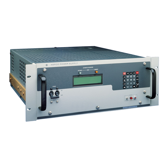
- Page 15 FIGURE 1-1. ATE-DMG SERIES PROGRAMMABLE POWER SUPPLY ATE-DMG020613...
- Page 16 (ix Blank)/x ATE-DMG020613...
-
Page 17: Section 1- Introduction
SECTION 1- INTRODUCTION SCOPE OF MANUAL This manual contains instructions for the installation, operation and maintenance of the ATE series of voltage and current stabilized d-c power supplies, manufactured by Kepco, Inc., Flush- ing, New York, U.S.A. GENERAL DESCRIPTION The Kepco ATE-DMG with programmable overvoltage protector is a precision stabilized power supply which can deliver either stabilized output voltage or current. -
Page 18: Input Characteristics
OUTPUT IMPEDANCE VOLTAGE MODE OUPUT IMPEDANCE CURRENT MODE MODEL SERIES L SHUNT C VOLTS AMPS SERIES R SHUNTR SLOW FAST SLOW FAST SIZE “E” FULL-RACK (1000 Watt) ATE 6-100DMG 0-100 1.2µΩ 0.5µH 5µH 12kΩ 22000µF 15µF ATE 15-50DMG 0-15 0-50 6µΩ 0.5µH 5µH 30kΩ... -
Page 19: Physical Characteristics
TABLE 1-2. ATE-DMG SERIES SPECIFICATIONS (Continued) SPECIFICATION RATING/DESCRIPTION CONDITION OUTPUT CHARACTERISTICS (CONTINUED) Hardware Overvolt- Type Crowbar age Protection Control range 1.6% or 3V (whichever is Local (manual) (OVP) greater) to 110%Eo max. Trigger time: normal 50 microseconds Slow mode Trigger time: delayed 500 microseconds Fast mode Threshold: Minimum 0.5 volts, or 2% Eo max. - Page 20 MAXIMUM MAXIMUM MAXIMUM MAXIMUM MODEL NUMBER OVERVOLTAGE OVERCURRENT MODEL NUMBER OVERVOLTAGE OVERCURRENT SETTING SETTING SETTING SETTING ATE 6-100DMG 6.5V 110A ATE 55-20DMG ATE 15-50DMG 16.5V ATE 75-15DMG ATE 25-40DMG ATE 100-10DMG 110V ATE 36-30DMG ATE 150-7DMG 165V 7.7A ATE-DMG OPER 020613...
-
Page 21: Features
TABLE 1-5. ATE STATIC SPECIFICATIONS OUTPUT EFFECTS VOLTAGE MODE OUTPUT EFFECTS CURRENT MODE OFFSETS INFLUENCE QUANTITY ∆ ∆ TYPICAL MAXIMUM TYPICAL MAXIMUM µ <0.0005% E max. <0.001% E max. <0.002% I max. <0.005% I max. SOURCE VOLTAGE (min. - max.) <1 <1nV <0.001% E... -
Page 22: Crowbar Circuit
There are no operator serviceable parts inside the case. Service must be referred to authorized personnel. Using the power supply in a manner not specified by Kepco. Inc. may impair the pro- tection provided by the power supply. Observe all safety precautions noted throughout this man- ual. - Page 23 TABLE 1-7. SAFETY SYMBOLS SYMBOL MEANING CAUTION: RISK OF ELECTRIC SHOCK. CAUTION: REFER TO REFERENCED PROCEDURE. WARNING INDICATES THE POSSIBILITY OF BODILY INJURY OR DEATH. CAUTION INDICATES THE POSSIBILITY OF EQUIPMENT DAMAGE. FIGURE 1-2. MECHANICAL OUTLINE DRAWING (SHEET 1 OF 2) ATE-DMG OPER 020613...
- Page 24 FIGURE 1-2. MECHANICAL OUTLINE DRAWING (SHEET 2 OF 2) ATE-DMG OPER 020613...
-
Page 25: Section 2 - Installation
SECTION 2 - INSTALLATION UNPACKING AND INSPECTION This instrument has been thoroughly inspected and tested prior to packing and is ready for operation. After carefully unpacking, inspect for shipping damage before attempting to operate. Perform the preliminary operational check as outlined in PAR. 2.5 below. If any indication of damage is found, file an immediate claim with the responsible transport service. - Page 26 FIGURE 2-1. ATE-DMG FULL RACK SERIES FRONT PANEL ATE-DMG 020613...
- Page 27 TABLE 2-2. REAR PANEL TERMINATIONS FIGURE 2-2 TERMINATION FUNCTION INDEX NO. GPIB (IEEE 488) Interface Allows digital control of power supply and provides digital indication of status and connector power supply output. See Table 2-4 for input/output pin assignments. Interconnection Assembly Used to gain access to internal circuitry for fast mode conversion, troubleshooting, and parallel/serial connections.
- Page 28 TABLE 2-3. INTERNAL CONTROLS AND THEIR FUNCTIONS REFERENCE CONTROL PURPOSE DESIGNATION CAUTION: Adjustment of any internal control will affect digital control of the output voltage and invalidate factory calibration (refer Calibration, Section 4). lo MAX Maximum Output Current Eo LAG Voltage Channel Stability Control Eo ZERO Voltage Channel Zero Control...
-
Page 29: Source Power Requirements
TABLE 2-4. INPUT/OUTPUT PIN ASSIGNMENTS FOR REMOTE CONTROL CONNECTOR SIGNAL NAME FUNCTION I/O Line I/O Line I/O Line I/O Line End or Identify Data Valid NRFD Not Ready for Data NDAC Not Data Accepted Interface Clear Service Request Attention IEEE 488 SHIELD Shield PORT... -
Page 30: Cooling
COOLING The power transistors and rectifiers in the ATE power supplies are maintained within their oper- ating temperature range by means of special heat sink assemblies, cooled by internal fans. SIDE PANEL OPENINGS AND THE TOP OF THE CASE MUST BE KEPT CLEAR FROM OBSTRUCTIONS TO INSURE PROPER AIR CIRCULATION. -
Page 31: Installation
7. Use number keys to enter rated maximum voltage (e.g. for ATE 25-40DMG, 25V is the rated maximum voltage) and press ENTER. Output voltage will be displayed at bottom left of LCD. " ç 8. Use keys as necessary to adjust output precisely to rated maximum voltage. Ver- ify DVM voltage reading agrees with displayed voltage on LCD within 0.01% of rated maxi- mum (see associated instruction manual). -
Page 32: Precautions
vide for low output noise, excellent voltage stability and good transient response. In the “fast” mode, the output and main feedback capacitors are completely removed, thereby providing the characteristics of a wide-band amplifier, ideal for applications requiring a current stabilizer or for high speed voltage or current programming. -
Page 33: Operating Configuration
NOTE: NUMBERS IN CIRCLES REFER TO STEPS OF PAR. 2.7.4. FIGURE 2-6. REQUIRED STEPS FOR ATE “FAST MODE” CONVERSION OPERATING CONFIGURATION The operating configuration can be determined by pressing MENU on the front panel keypad six times (with the unit in command entry status). -
Page 35: Section 3 - Operation
WARNING KEEP INSTRUMENT GROUNDED WHILE IT IS CONNECTED TO THE A-C POWER SOURCE. Kepco power supplies with a flexible a-c power cord are equipped with a 3-prong safety plug, which must be connected to a grounded a-c power outlet. 3.1.2... -
Page 36: Power Supply/Load Interface
however, equally valid for either output side grounded. Care should be taken in measuring the ripple and noise at the power supply output or at the load, Measuring devices which are a-c line operated often introduce ripple and noise into the circuit. In the case where the load must be kept completely off ground (d-c isolated) or it must be oper- ated above ground potential, grounding can be accomplished by means of a suitable capacitor connected from either side of the power supply output to the signal ground. -
Page 37: Load Connection
3.2.1 GENERAL Kepco has provided a group of terminals on the programming connector PC-12 and on the bar- rier strip (TB210) at the rear of the power supply, which permit maximum flexibility in power sup- ply/load interface techniques. Although all applications tend to exhibit their own problems, the basic interconnections described may be used as a general guide in the interconnection between power supply and load. - Page 38 FIGURE 3-2. STANDARD JUMPER LINK CONNECTIONS FOR LOCAL (FRONT PANEL) CONTROL OF OUTPUT VOLTAGE, OUTPUT CURRENT AND VP CROWBAR LEVEL (SLOW MODE) Note: Connection diagrams in Section 3 are applicable for full-rack ATE power supplies. These diagrams represent partial views of the ATE rear panel. The AC source input, interconnection adapter assembly A11 and the GPIB connector are deleted to simplify the presentation.
-
Page 39: Load Connection, Method I (Local Error Sensing)
FIGURE 3-3. LOAD CONNECTION METHOD I, LOCAL ERROR SENSING 3.2.3 LOAD CONNECTION, METHOD II (REMOTE ERROR SENSING) To avoid excessive output effects at remote loads, error sensing must be used. A twisted, shielded pair of wire from the sensing terminals directly to the load will compensate for load wire voltage drops up to 0.5 volt per wire (refer to Figure 3-4). -
Page 40: Load Connection, Method Iii
FIGURE 3-4. LOAD CONNECTION, METHOD II USING REMOTE ERROR SENSING. 3.2.4 LOAD CONNECTION, METHOD III This method is suitable if step changes in the load are expected if, for example, the load is rap- idly changing in value and maximum dynamic performance is expected directly at the load ter- minals. -
Page 41: Overvoltage Crowbar, Setup And Check
OVERVOLTAGE CROWBAR, SETUP AND CHECK The overvoltage crowbar circuit protects the load from momentary or long-term overvoltages. The crowbar SCR conducts across the power supply output, and the A-C POWER SWITCH/CIRCUIT BREAKER is tripped if such overvoltages occur. The setting of the front panel LEVEL control determines the “threshold”... -
Page 42: Front Panel Keypad And Lcd
3.4.1 FRONT PANEL KEYPAD AND LCD (SEE FIGURE 2-1) The front panel keypad is comprised of 24 key, 13 dedicated to command functions, 5 dedicated to data functions, and 6 keys that have both command and data functions When the power sup- ply is in command entry status the command functions are effective;... - Page 43 NOTE: Keys with dual functions are labeled with both a command and a number. The com- mand label is referred to when the unit is in command entry status; the number is referred to when the unit is in data entry status. TABLE 3-1.
-
Page 44: Turning The Power Supply On
( O ) shuts the power supply off. When the power supply is turned on, the LCD first shows the power supply type, e.g., Kepco ATE25-40 GPIB addr. = nn, where nn is the GPIB address (factory default GPIB address = 6).The LCD then shows the power on defaults (see Figure 3-6). -
Page 45: Setting Local Mode
output current set to a minimum value (1-2% of I max). Power on defaults also include setting maximum values for overcurrent and overvoltage protection indicated in Table 1-4. 0.000V 0.000A NOTE: indicates blinking colon (:), Command Entry status indicates blinking equal sign (=), Data Entry status FIGURE 3-6. -
Page 46: Setting Output Voltage Or Current
(1-2% of I max), overcurrent and overvoltage protection set to the maximum values per Table 1-4. The power supply remains in command entry status. 3.4.8 SETTING OUTPUT VOLTAGE OR CURRENT V SET and I SET set output voltage and current limit, respectively, when the unit is in constant voltage (CV) mode and set voltage limit and output current, respectively, when the unit is in con- stant current (CC) mode. -
Page 47: Changing Protection Delay
3.4.10 CHANGING PROTECTION DELAY The overvoltage and overcurrent protection normally trips immediately upon detection of an overvoltage/overcurrent condition. However, changing output settings (particularly with reactive loads) large transients can cause inadvertent tripping of the protection. For this reason, tripping of the overvoltage/overcurrent protection can be delayed approximately 8 seconds after the out- put is changed. -
Page 48: Recalling Stored Output Settings
3.4.13 RECALLING STORED OUTPUT SETTINGS With the power supply in command entry status , press RECALL. The LCD reads RECALL nn where nn is the memory location holding the settings to be retrieved. Press ENTER or CLEAR to exit without changing setting. Enter memory location (from 1 to 40) and press ENTER. -
Page 49: Time Interval Accuracy
value, or enter new value (between 0.01 and 300 seconds) and press ENTER to accept new value or press CLEAR to exit without changing value. The unit returns to command entry status . Refer to PAR. 3.4.15.1.2 if accuracy of time values is important. 3.4.15.1.2 TIME INTERVAL ACCURACY The accuracy of the time interval is ±2.5%. - Page 50 " press EDIT PROG, enter 14, then press ENTER. Press until LCD reads ViewVAL Mem14 . Enter 5 and press ENTER. When the program runs, it will start at location 05, NEXT STEP continue to 14, then loop back to the location 05, and repeat indefinitely. TABLE 3-2.
-
Page 51: Running A Program Once
3.4.15.5 RUNNING A PROGRAM ONCE To set up a program to stop after running once, modify the program (see PAR. ) and go to the last memory location to be executed and set the NEXT STEP address to 0. For example, with the power supply in command entry status , press EDIT PROG. -
Page 52: Analog Remote Programming
5x2 housing (not sup- plied). The following parts are recommended, but not supplied: ribbon cable: AMP 746285-1 (Kepco P/N 142-0246); Housing for discrete wires: Molex 39-01-2100 (Kepco P/N 142-0434); Pins: Molex 39-00-0039 (Kepco P/N 107-0290, 4 ea.). -
Page 53: Digital Remote Mode Programming
1. Connect a 0 to 10V voltage reference to A11J5 pin 1 (pin 6 common); 0V programs the out- put voltage to zero, 10V programs output voltage to full scale. 2. Connect a 0 to 1V current reference to A11J5 pin 2 (pin 8 common), 0V programs the output current to zero, 1V programs output current to full scale. - Page 54 TABLE 3-5. IEEE 488 (GPIB) BUS INTERFACE FUNCTIONS SUBSET FUNCTION COMMENTS SYMBOL Source Handshake Complete Capability (Interface can receive multiline messages) Acceptor Handshake Complete Capability (Interface can receive multiline messages) Basic talker, serial poll, unaddress if MLA (My Listen Address) (one-byte Talker address) Listener...
-
Page 55: Dcl Control
3.6.5 PROGRAMMING TECHNIQUES TO OPTIMIZE PERFORMANCE Kepco's auto-crossover digital supplies can operate in either voltage mode with current limit, or current mode with voltage limit. The operating mode is determined by the voltage and current commands received, as well as the load. Each time voltage and current commands are received, the unit must evaluate the commands and the load conditions to determine the proper operating mode. -
Page 56: Scpi Programming
This will improve response time and reduce undesirable transients. For those power supplies that employ relays (Kepco's MBT with “R” option, MAT and MST) this will also increase the life of the relay. -
Page 57: Abort Subsystem
subsystem commands used in the ATE-DMG Power Supply with the “root” at the left side, and specific commands forming the branches. The following paragraphs introduce the subsystems; subsystem commands are defined and explained in Appendix B. 3.7.3.1 ABORT SUBSYSTEM This subsystem allows pending trigger levels to be cancelled. 3.7.3.2 DIAG SUBSYSTEM This subsystem is used to enable/disable external analog control of the output. -
Page 58: Trigger Subsystem
SCPI program messages (commands from controller to power supply) consist of one or more message units ending in a message terminator (required by Kepco power modules). The message terminator is not part of the syntax; it is defined by the way your programming language indi- cates the end of a line (“newline”... -
Page 59: System Subsystem
ROOT : (colon) STATus subsystem ABORt subsystem [SOURce:] subsystem STATus ABORt [SOURce:] :OPERation VOLTage :CONDition? INITiate subsystem [:LEVel] :ENABle val [:IMMediate] INITiate :ENABle? [:AMPLitude] val [:IMMediate] [:EVENt]? [:AMPLitude]? MIN, MAX :CONTinuous bool :PRESet :TRIGgered :CONTinuous? :QUEStionable [:AMPLitude] val :CONDition? [:AMPLitude]? MIN, MAX CALibrate subsystem :ENABle val :PROTection... -
Page 60: Keyword
3.7.4.1 KEYWORD Keywords are instructions recognized by a decoder within the ATE-DMG, referred to as a “parser.” Each keyword describes a command function; all keywords used by the ATE-DMG are listed in Figure 3-8. Each keyword has a long form and a short form. For the long form the word is spelled out com- pletely (e.g. - Page 61 You must use the rules above when using keywords. Using an arbitrary short form such as ENABL for ENAB (ENABLE) or IMME for IMM (IMMEDIATE) will result in an error. Regardless of which form chosen, you must include all the letters required by that form. To identify the short form and long form in this manual, keywords are written in upper case let- ters to represent the short form, followed by lower case letters indicating the long form (e.g., IMMediate, EVENt, and OUTPut).
-
Page 62: Message Terminator
• new line (<NL>), ASCII 10 (decimal) or 0A (hex) NOTE: Kepco power supplies require a message terminator at the end of each program mes- sage. The examples shown in this manual assume a message terminator will be added at the end of each message. Where a message terminator is shown it is represented as <NL>... -
Page 63: Program Message Syntax Summary
3.7.6 PROGRAM MESSAGE SYNTAX SUMMARY • Common commands begin with an asterisk (*). • Queries end with a question mark (?). • Program messages consist of a root keyword and, in some cases, one or more message units separated by a colon (:) followed by a message terminator. Several message units of a program message may be separated by a semicolon (;) without repeating the root keyword. - Page 64 /**************************************************************************/ Sample Program For KEPCO power supply, using National Instruments GPIB interface card and IBM PC or compatible computer /**************************************************************************/ #include <stdio.h> #include "decl.h" char rd_str[80]; // Input buffer char dat_str[80]; // Output buffer bd,adr; main() { adr = ibfind("DEV6");...
-
Page 65: Section 4 - Calibration
Shunt Resistor: During the calibration procedure the LCD displays the minimum require- ments for the shunt resistor. However, to avoid problems due to drift caused by heat dis- sipation at higher power levels, Kepco recommends the items listed in Table 4-1 TABLE 4-1. SUGGESTED SENSE RESISTORS... -
Page 66: Voltage Calibration
For voltage calibration all loads must be disconnected and the sense terminals connected to the corresponding output terminals. The digital voltmeter will be connected to the output of the power supply. For current calibration after disconnecting all loads an appropriate shunt resistor will be connected across output terminals and the digital voltmeter will be connected across the sense terminals of the shunt resistor. -
Page 67: Changing The Calibration Password
NOTE: If LCD reads CAN’T ADJUST FULL SCALE, adjust I max control R18 for current equal to I max. Depress ENTER and RESET, then restart current calibration. – ATE 6-100DMG: 1.000V if 0.01 Ohm resistor, 0.500V if 0.05 Ohm resistor – ATE 15-70DMG: 0.700V – ATE 25-40DMG: 1.600V –... -
Page 68: Restoring Previous Calibration Values
1. If the unit is not in command entry status , press CLEAR or RESET to put the unit in com- mand entry status. 2. Press MENU key five times. LCD reads Change Passw. OldPass . 3. Enter the old password and press ENTER. Then enter the new 4-digit Password and press ENTER. -
Page 69: Appendix A - Ieee 488.2 Command/Query Definitions
APPENDIX A - IEEE 488.2 COMMAND/QUERY DEFINITIONS INTRODUCTION This appendix defines the IEEE 488.2 commands and queries used with the ATE Power Supply These commands and queries are preceded by an asterisk (*) and are defined and explained in Fig- ures A-1 through A-14, arranged in alphabetical order. -
Page 70: Ese? - Standard Event Status Enable Query
<Manufacturer>, <Model>, <Serial Number>, <Firmware revision> where: <Manufacturer> = KEPCO, <Model> = ATE-V V- AA (V V is Vmax, AA is Imax, e.g. 100-10 or 6-100), <Serial Number> = MM,DD,YY-SSS (MM - month, DD - day, YY - year, SSS - serial number in that day) <Firmware revision>=n.m (n.m revision, e.g, 1.0) (See example, Figure A-1.) -
Page 71: Opt? - Options Query
*OPT? *OPT? — OPTIONS QUERY Syntax: *OPT? Returns string determined by power supply model. Description: Causes the power supply to return an ASCII string which defines the functionality of the power supply. The functionality is defined as follows: STRING DATA MEANING Support for CALibrate command is present. -
Page 72: Sre - Service Request Enable Command
Returns 32 (bit 5 set), indicating Command Error has occurred since the last time the register was read. *IDN? Power supply returns: KEPCO,ATE-100-10, 082495-001, 1.0. *OPC Allows status bit 0 to be set when pending operations complete VOLT 21;CURR 3... -
Page 73: Sre? - Service Request Enable Query
TABLE A-3. SERVICE REQUEST ENABLE AND STATUS BYTE REGISTER BITS OPER Operation Status Summary Master Status Summary Request for Service CONDITION OPER QUES Event Status Byte summary Message available QUES QUEStionable Status Summary ERR QUE 1 or more errors occurred (see VALUE PAR. -
Page 75: Appendix B - Scpi Command/Query Definitions
APPENDIX B - SCPI COMMAND/QUERY DEFINITIONS INTRODUCTION This appendix defines the SCPI subsystem commands and queries used with the ATE Power Supply. Subsystem commands are defined in PAR. B.2 through B.96, arranged in groups as they appear in the tree diagram, Figure 3-7. Table B-1 provides a quick reference of all SCPI subsystem commands and queries used in the Interface Card. -
Page 76: Abort Command
ABOR ABORt COMMAND Syntax: Short Form: ABOR Long Form: ABORt Description: Cancels previously stored trigger levels, resets WTG. The ABORt command cancels any pending trigger levels previously stored by the CURR:TRIG or VOLT:TRIG commands. The pending level is set equal to the corresponding immediate value. ABORt also resets the WTG (Wait TriGger) bit in the Operation Condition status register. -
Page 77: Cal:curr:lev
CAL:CURR:LEV CALibrate:CURRent:LEVel COMMAND Syntax: Short Form: CAL:CURR:LEV {MIN | MAX} Long Form: CALibrate:CURRent:LEVel {MIN | MAX} Description: Selects Current calibration, only effective with power supply in Calibrate status. CAL:CURR:LEV MIN selects Current Zero Calibration. CAL:CURR:LEV MAX selects Current Full Scale Calibration. Normally Current Zero is done first, then Current Full Scale Calibration. Related Commands: CAL:STAT, CAL:PASS, CAL:VOLT, CAL:CURR, CAL:ZERO, CAL:SAVE. -
Page 78: Calibrate:password Command
CAL:PASS CALibrate:PASSword COMMAND Syntax: Short Form: CAL:PASS new_password (new_password is 4 digits) Long Form: CALibrate:PASSword new_password (new_password is 4 digits) Description: Changes the password used to put the power supply in Calibrate status. To execute this com- mand, the power supply must be in Calibrate status (see CAL:STAT). password = 4 digits, required to enter Calibrate status. -
Page 79: Calibrate:voltage[:Data] Command
CAL:VOLT B.10 CALibrate:VOLTage[:DATA] COMMAND Syntax: Short Form: CAL:VOLT[:DATA] {0 | 1 | 2 | 3} Long Form: CALibrate:VOLTage[:DATA] {0 | 1 | 2 | 3} Increases or decreases output voltage during calibration only. Description: CAL:VOLT[:DATA] 0 decreases output voltage by small increment. CAL:VOLT[:DATA] 1 increases output voltage by small increment. -
Page 80: Display:contrast? Query
DISP:CONT 0.9 Sets LCD contrast value to 0.9. DISP:CONT? Returns 0.9. DISP:MODE NORM Changes LCD to Normal metering mode. DISP:MODE? Returns NORMAL. DISP:MODE TEXT Changes LCD to Text mode. DISP:TEXT “**ATE IS IN USE” Second line of display reads **ATE IS IN USE. DISP:MODE? Returns “TEXT”... -
Page 81: Initiate[:Immediate] Command
INIT[:IMM] B.20 INITiate[:IMMediate] COMMAND Syntax: Short Form: INIT:[IMM] Long Form: INITiate[:IMMediate] Description: Enables a single trigger. If INIT:CONT is OFF, then INIT[:IMM] arms the trigger system for a single trigger. If INIT:CONT is ON, then the trigger system is continuously armed and INIT[:IMM] is redun- dant. -
Page 82: Sour:]List:current:protect Command
LIST:CURR:PROT B.26 [SOUR:]LIST:CURRent:PROTect COMMAND Syntax: Short Form: LIST:CURR:PROT<num_value> Long Form: LIST:CURRent:PROTect <num_value> <num_value> = digits with decimal point and Exponent Description: Sets the current protection (Amps) value for the memory location selected by LIST:IND. If the value is out of the acceptable current range for the power supply model, an error message: -222,”Data out of range”... -
Page 83: Sour:]List:dwell? Query
LIST:DWEL? B.29 [SOUR:]LIST:DWELl? QUERY Syntax: Short Form: LIST:DWEL? Long Form: LIST:DWELl? Return Value: <value> (0.01 to 300) LIST:IND B.30 [SOUR:]LIST:INDex COMMAND Syntax: Short Form: LIST:IND <int_value> (from 1 to 40) Long Form: LIST:INDex <int_value> (from 1 to 40) Description: Selects one 40 memory locations for viewing or modification of parameter selected by subse- quent LIST:CURR, LIST:CURR:PROT, LIST:VOLT, LIST:VOLT:PROT commands or queries. -
Page 84: Sour:]List:voltage Command
LIST:VOLT B.36 [SOUR:]LIST:VOLTage COMMAND Syntax: Short Form: LIST:VOLT[:LEV] <exp_value> Long Form: LIST:VOLTage[:LEVel] <exp_value> <exp_value> = digits with decimal point and Exponent, e.g., 2.71E+1 for 27.1 Description: Sets the voltage value for the memory location selected by LIST:IND. If the value is out of the acceptable voltage range for the power supply model, an error message: -222,”Data out of range”... -
Page 85: Output[:State] Command
racy of the measurement if nn,nn is added after the question mark; the power supply accepts this for- mat but sets the command warning bit (13) in the status questionable register and ignores the extra characters. (See example, Figure B-1.) OUTP B.42 OUTPut[:STATe] COMMAND Syntax:... -
Page 86: Query
READ:CURR? B.48 READ[:SCALar]:CURRent[:DC]? QUERY Syntax: Short Form: READ[:SCAL]:CURR[:DC]? Long Form: READ[:SCALar]:CURRent[:DC]? Return Value: <num_value> (digits with decimal point and Exponent) Description: Measures actual current. Same as MEAS:CURR? (see PAR. B.40) READ:VOLT? B.49 READ[:VOLTage][:SCALar][:DC]? QUERY Syntax: Short Form: READ[:SCAL]:VOLT[:DC]? Long Form: READ[:SCALar]:VOLTage[:DC]? Description: Measures actual voltage. -
Page 87: Source:]Current:protection[:Level] Command
CURR:MODE B.54 [SOURce:]CURRent:[:LEVel]MODE COMMAND Syntax: Short Form: [SOUR:]CURR[:LEV]:MODE {FIX | EXT} Long Form: [SOURce:]CURRent[:MODE {FIXed | EXTernal} Description: Establishes whether control of the output current is via keypad or GPIB commands (FIXED) or via external analog 0 to 1V reference (EXTERNAL). Setting is stored in NVRAM and retained upon subsequent power up. -
Page 88: Source:]Current:protection[:Level]? Query
CURR:PROT? B.57 [SOURce:]CURRent:PROTection[:LEVel]? QUERY Syntax: Short Form: [SOUR:]CURR:PROT[:LEV]? {MIN | MAX} Long Form: [SOURce:]CURRent:PROTection[:LEVel]? {MIN | MAX} Return Value: <exp_value> = digits with decimal point and Exponent, e.g., 2.71E+1 for 27.1 Description: Returns value representing current protection level.CURR:PROT? returns value set by CURR:PROT. -
Page 89: Source:]Voltage[:Level][:Immediate][:Amplitude]? Query
VOLT? B.63 [SOURce:]VOLTage[:LEVel][:IMMediate][:AMPlitude]? QUERY Syntax: Short Form: [SOUR:]VOLT[:LEV][:IMM][:AMP]? {MIN | MAX} Long Form: [SOURce:]VOLTage[:LEVel][:IMMediate][:AMPlitude]? {MIN | MAX} Description: Identifies programmed voltage, maximum allowable voltage, or minimum voltage (always 0). The VOLT? query returns the programmed value of voltage. Actual output voltage will depend on load conditions. -
Page 90: Source:]Voltage:protection[:Level] Command
VOLT:MODE? B.69 [SOURce:]VOLTage:[:LEVel]MODE? QUERY Syntax: Short Form: [SOUR:]VOLT[:LEV]:MODE? Long Form: [SOURce:]VOLTage[:LEVel]MODE]? Return Value: FIXED or EXTERNAL Description: Returns FIXED or EXTERNAL depending on whether voltage control is from the keypad or GPIB interface (FIXED or from an external analog reference voltage (EXTERNAL). VOLT:PROT B.70 [SOURce:]VOLTage:PROTection[:LEVel] COMMAND Syntax:... -
Page 91: Source:]Voltage:protection:clear Command
returns maximum voltage protection value (see Table 1-2); this value is determined at the factory and cannot be changed by the user. VOLT:PROT? MIN returns the minimum voltage protection value (always 0). (See example, Figure B-6.) VOLT:PROT:CLE B.72 [SOURce:]VOLTage:PROTection:CLEar COMMAND Syntax: Short Form: [SOUR:]VOLT:PROT:CLE Long Form: [SOURce:]VOLTage:PROTection:CLEar... -
Page 92: Status:opereration:enable? Query
STAT:OPER:ENAB? B.77 STATus:OPEReration:ENABle? QUERY Syntax: Short Form: STAT:OPER:ENAB? Long Form: STATus:OPERation:ENABle? Return Value: <int_value> 0 to 1313 (1 + 32 + 256 + 1024). Description: Reads Operation Enable Register (see Table B-2). Returns value of Operation Enable Register bits. Bit set to 1 = function enabled (active, true); bit reset to 0 = function disabled (inactive, false). (See example, Figure B-7.) STAT:OPER? B.78 STATus:OPERation[:EVENt] QUERY... -
Page 93: Status:questionable[:Event]? Query
STAT:QUES? B.80 STATus:QUEStionable[:EVENt]? QUERY Syntax: Short Form: STAT:QUES[EVEN]? Long Form: STATus:QUEStionable[EVENT]? Return Value: <int_value> actual register value Description: Indicates questionable events that occurred since previous STAT:QUES? query. Returns the value of the Questionable Event register (see Table B-3). The Questionable Event register is a read-only register which holds (latches) all events. -
Page 94: System:error:code? Query
SYST:ERR:CODE? B.85 SYSTem:ERRor:CODE? QUERY Syntax: Short Form: SYST:ERR:CODE?] Long Form: SYSTem:ERRor:CODE? Description: Returns the three character error code without the ASCII definition string. The error codes are defined in table B-4 (See example, Figure B-1.) SYST:ERR:CODE:ALL? B.86 SYSTem:ERRor:CODE:ALL? QUERY Syntax: Short Form: SYST:ERR:CODE:ALL?] Long Form: SYSTem:ERRor:CODE:ALL? Return Value:... - Page 95 TABLE B-4. ERROR MESSAGES ESR ERROR BIT SET ERROR MESSAGE EXPLANATION (SEE PAR. A.5) 0,“No error” None No error. -100,“Command error” Command and data understood, but more informa- Command Error bit 5 tion included which is not recognized. -102,”Syntax error” First 4 characters recognized, subsequent charac- Command Error bit 5 ters not recognized.
-
Page 96: System:password:cenable Command
SYST:PASS:CEN B.91 SYSTem:PASSword:CENable COMMAND Syntax: Short Form: SYST:PASS:CEN <val> Long Form: SYSTem:PASSword:CENable <val> Description: Sets the password enable state if the value matches the current password. This command allows other commands such as *SAV 41 to operate. SYST:PASS:CDIS B.92 SYSTem:PASSword:CDISable COMMAND Syntax: Short Form: SYST:PASS:CDIS <val>... -
Page 97: System:set Command
Sending SYST:SET RLX allows the power supply to accept special debug and troubleshooting com- mands (for KEPCO use only - e.g., after sending SYST:SET RLX the power supply will respond to the $vda? command by returning the value of the internal D/A converter for voltage). Sending SYST:SET STR disables the special debug and troubleshooting commands.
Need help?
Do you have a question about the ATE 6-100DMG and is the answer not in the manual?
Questions and answers