Table of Contents
Advertisement
Quick Links
OPERATOR'S MANUAL
HIGH POWER BIPOLAR POWER SUPPLY
(LOW NOISE, RIPPLE, DRIFT AND TEMPERATURE COEFFICIENT)
KEPCO INC.
An ISO 9001 Company.
IMPORTANT NOTES:
1)
This manual is valid for the following Firmware Versions:
FIRMWARE VERSION
3.05 and higher
2)
A Change Page may be included at the end of the manual. All applicable changes and
revision number changes are documented with reference to the equipment serial num-
bers. Before using this Instruction Manual, check your equipment firmware version num-
ber to identify your model. If in doubt, contact your nearest Kepco Representative, or the
Kepco Documentation Office in New York, (718) 461-7000, requesting the correct revision
for your particular model and firmware version number.
3)
The contents of this manual are protected by copyright. Reproduction of any part can be
made only with the specific written permission of Kepco, Inc.
Data subject to change without notice.
©2015, KEPCO, INC
P/N 243-1293-y
KEPCO, INC. 131-38 SANFORD AVENUE FLUSHING, NY. 11355 U.S.A. TEL (718) 461-7000 FAX (718) 767-1102
BOP-GL 1KW
OPTIMIZED FOR INDUCTIVE LOADS
BOP-GL 1KW
POWER SUPPLY
ORDER NO.
email: hq@kepcopower.com World Wide Web: http://www.kepcopower.com
MODEL
NOTE.
KEPCO
THE POWER SUPPLIER™
®
Advertisement
Table of Contents

Related Manuals for KEPCO BOP-GL 1KW


Summary of Contents for KEPCO BOP-GL 1KW
-
Page 1: Power Supply
Data subject to change without notice. KEPCO ® ©2015, KEPCO, INC P/N 243-1293-y THE POWER SUPPLIER™ KEPCO, INC. 131-38 SANFORD AVENUE FLUSHING, NY. 11355 U.S.A. TEL (718) 461-7000 FAX (718) 767-1102 email: hq@kepcopower.com World Wide Web: http://www.kepcopower.com... -
Page 3: Declaration Of Conformity
Standard to which Conformity is declared: EN61010-1:1993 (Safety requirements for electrical equipment for measurement, control and laboratory use) Manufacturer's Name and Address: KEPCO INC. 131-38 SANFORD AVENUE FLUSHING, N.Y. 11355 USA Importer's Name and Address: Type of Equipment: Component Power Supply Model No.:... - Page 4 There are no user or operator serviceable parts within the product enclosure. Refer all servicing to qualified and trained Kepco service technicians. 228-1529 COND/CONFORM 111315...
-
Page 5: Safety Instructions
SAFETY INSTRUCTIONS 1. Installation, Operation and Service Precautions This product is designed for use in accordance with EN 61010-1 and UL 3101 for Installation Category 2, Pollution Degree 2. Hazardous voltages are present within this product during normal operation. The prod- uct should never be operated with the cover removed unless equivalent protection of the operator from accidental contact with hazardous internal voltages is provided: There are no operator serviceable parts or adjustments within the product enclosure. -
Page 6: Safety Messages
Service must be referred to authorized personnel. Using the power supply in a manner not specified by Kepco. Inc. may impair the protection provided by the power supply. Observe all safety precautions noted throughout this manual. The following table lists symbols used on the power supply or in this manual where applicable. - Page 7 LIST OF WARNINGS AND CAUTIONS PAGE WARNING/CAUTION WARNING: For inductive loads, and especially superconducting magnet type loads, the inherent offset of the BOP in the OFF state may generate significant current in the circuit. A properly rated switch in parallel with a resistor must be connected between the power supply and the load.
- Page 8 LIST OF WARNINGS AND CAUTIONS PAGE WARNING/CAUTION CAUTION: it is recommended that source power of external equipment connected to the Analog Port be applied through an isolating transformer to avoid ground loops or possible damage to the BOP due to incorrect equipment a-c wiring (e.g., defeating of ground connection).
- Page 9 LIST OF WARNINGS AND CAUTIONS PAGE WARNING/CAUTION CAUTION: Before connecting a load, note that the unit is will power-up with the con- figuration set by the power-up switches accessible through the top cover (see Table 2-2 for switch settings). Verify that these power-up settings are compatible with your load (see Figure 2-2 and Table 2-2 for switch set- tings).
-
Page 11: Table Of Contents
TABLE OF CONTENTS SECTION PAGE SECTION 1 - INTRODUCTION Scope of Manual ............................. 1-1 General Description..........................1-1 Specifications ............................1-1 Remote Control ............................1-13 Features ..............................1-13 1.5.1 Digital Calibration..........................1-13 1.5.2 voltage/current Protection........................1-13 1.5.3 Waveforms............................1-13 1.5.4 Saving and Recalling Settings ......................1-14 1.5.5 External Reference (Analog Control).................... - Page 12 TABLE OF CONTENTS SECTION PAGE SECTION 3 - OPERATION General ..............................3-1 Power-up Settings ..........................3-1 3.2.1 Changing the Default Power-up Settings..................3-2 Power Supply Basics ..........................3-2 3.3.1 Controls and Indicators ........................3-2 3.3.2 Turning the Power Supply On......................3-3 3.3.2.1 Reset Power-up ..........................
- Page 13 TABLE OF CONTENTS SECTION PAGE 3.6.3.1.1 Changing the GPIB Address ....................3-31 3.6.3.1.2 Configure Device Clear (DCL) Control..................3-32 3.6.3.1.3 Determining Whether *RST Command sets the Output Off or On..........3-32 3.6.4 RS232-C Operation ........................... 3-32 3.6.4.1 Serial Interface..........................3-32 3.6.4.2 RS 232 Implementation ....................... 3-32 3.6.4.2.1 XON XOFF Method.........................3-34 3.6.4.2.2...
- Page 14 TABLE OF CONTENTS SECTION PAGE Operator Troubleshooting........................3-50 SECTION 4 - CALIBRATION General ..............................4-1 Test Equipment Requirements ....................... 4-3 Calibration using Remote SCPI commands via GPIB or RS 232 Interface ..........4-3 4.3.1 Calibration Procedure using SCPI Commands................. 4-5 4.3.2 Calibration of Series- or Parallel-Connected Units ................
- Page 15 TABLE OF CONTENTS SECTION PAGE B.24 [SOUR :]CURR [:LEV ]:LIM :NEG? Query................... B-9 B.25 [SOUR :]CURR [:LEV ]:LIM :POS Command ................B-9 B.26 [SOUR :]CURR [:LEV ]:LIM :POS? Query................... B-9 B.27 [SOUR :]CURR :MODE Command....................B-10 B.28 [SOUR :]CURR :MODe? Query...................... B-10 B.29 [SOUR :]CURR...
- Page 16 TABLE OF CONTENTS SECTION PAGE B.81 [SOUR :]LIST:VOLT :APPL ? Query ................B-24 B.82 [SOUR :]LIST:VOLT :POIN ? Query .................... B-24 B.83 [SOUR :]LIST:WAIT:HIGH Command ....................B-25 B.84 [SOUR :]LIST:WAIT:LEDGe Command ....................B-25 B.85 [SOUR :]LIST:WAIT:LOW Command....................B-25 ediate litude B.86 [SOUR :]VOLT...
- Page 17 TABLE OF CONTENTS SECTION PAGE word able B.138 SYST :PASS :CDIS Command ................... B-36 word B.139 SYST :PASS :NEW Command....................B-36 word B.140 SYST :PASS :STAT ? Query ..................... B-36 B.141 SYST :REM Command......................... B-36 B.142 SYST :REM ? Query........................B-36 urity ediate B.143...
- Page 18 LIST OF FIGURES FIGURE TITLE PAGE High Power BOP-GL Series Power Supply....................x BOP-GL Power Supply, Outline Drawing ....................1-11 BOP Output Characteristics ........................1-16 BOP-GL Series Rear Panel........................2-1 BOP-GL Top Cover Accessible Components .................... 2-3 Factory Default Power-up Switch Settings ....................2-10 Load Connections, Local Sensing......................
- Page 19 LIST OF TABLES TABLE TITLE PAGE BOP-GL 1000 Watt Model Parameters .......................1-1 BOP General Specifications ........................1-2 Equipment Supplied ............................1-15 Safety Symbols ............................1-15 Accessories ..............................1-17 Rear Panel Connector Functions ........................2-2 Power-Up Setup Switches ..........................2-3 Top Cover Calibration Adjustments ......................2-4 IEEE 1118 Connector Input/Output Pin Assignments .................2-4 Trigger Port Pin Assignments ........................2-5 External Protection Connector Input/Output Pin Assignments ..............2-5 RS232C PORT Input/Output Pin Assignments ...................2-6...
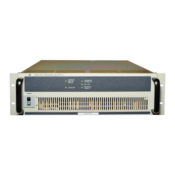
- Page 20 FIGURE 1-1. HIGH POWER BOP-GL SERIES POWER SUPPLY BOP-1K 111315...
-
Page 21: Section 1 - Introduction
This manual contains instructions for the installation, operation and servicing of the BOP-GL series of 1000 Watt rack-mounted, 4-quadrant bipolar, programmable, voltage and current stabi- lized d-c power supplies manufactured by Kepco, Inc., Flushing, New York, U.S.A. GENERAL DESCRIPTION The BOP-GL Series (Figure 1-1), are true 4-quadrant programmable voltage and current power supplies, meaning they are capable of both sourcing and sinking power. -
Page 22: Bop General Specifications
TABLE 1-2. BOP GENERAL SPECIFICATIONS SPECIFICATION RATING/DESCRIPTION CONDITION INPUT CHARACTERISTICS 200/220/230/240Va-c (1) a-c voltage nominal No setting required. Single phase or between (200-240 Va-c) 2 phases of a 3-phase system within 200- 240Va-c. range 176 - 264 Va-c Continuous; Input voltage outside range causes protection fault. - Page 23 TABLE 1-2. BOP GENERAL SPECIFICATIONS (Continued) SPECIFICATION RATING/DESCRIPTION CONDITION OUTPUT CHARACTERISTICS (Continued) Analog Programming Voltage 0.01% of rating • Voltage and Current limit in Voltage Mode accuracy and Current and Voltage Limit in Current Current Limit 0.1% of rating Mode. Current 0.01% of rating •...
- Page 24 TABLE 1-2. BOP GENERAL SPECIFICATIONS (Continued) SPECIFICATION RATING/DESCRIPTION CONDITION OUTPUT CHARACTERISTICS (Continued) Above rated output voltage (3) Error sensing 0.25V or 1% of voltage rating per wire (whichever is less) Transient recovery in maximum excursion 5% of nominal output nominal voltage, 50% load step voltage mode ...
- Page 25 TABLE 1-2. BOP GENERAL SPECIFICATIONS (Continued) SPECIFICATION RATING/DESCRIPTION CONDITION PROGRAMMING CHARACTERISTICS Analog I/O Port (6) Main channel –10V to +10V Full range output, 20K Ohm input impedance (see Table 2-12) (voltage or current) Protection Limit +1V to +10V 10% to 100% of Nominal Range. Input voltage channels: clamped to 12V through 1K ohms.
- Page 26 TABLE 1-2. BOP GENERAL SPECIFICATIONS (Continued) SPECIFICATION RATING/DESCRIPTION CONDITION PROGRAMMING CHARACTERISTICS (Continued) Digital control remote IEEE 488-2 (GPIB) and RS 232 SCPI remote RS 485 (BITBUS) IEEE 1118, used for series and parallel config- urations Status front panel Lights: Display Unit Status: POWER / FAULT/LIMIT (lights green for Power OK, lights red for Fault, lights orange for Limit).
- Page 27 TABLE 1-2. BOP GENERAL SPECIFICATIONS (Continued) SPECIFICATION RATING/DESCRIPTION CONDITION FUNCTION GENERATOR CHARACTERISTICS (Continued) Basic waveform parameters Sine: Frequency (Hz), Amplitude (Vp-p or Ap-p), Offset (Vd-c or Ad-c), Start Phase (°), Stop Phase (°). Triangular: Frequency (Hz), Amplitude (Vp-p or Ap-p), Offset (Vd-c or Ad-c), Start Phase (°), Stop Phase (°).
- Page 28 TABLE 1-2. BOP GENERAL SPECIFICATIONS (Continued) SPECIFICATION RATING/DESCRIPTION CONDITION FUNCTION GENERATOR CHARACTERISTICS (Continued) Amplitude Range Main Channel Voltage (Volts p-p) 0 to 2 x E O Sine, Triangle, Square, ±Ramp Current (Amperes 0 to 2 x I O Sine, Triangle, Square, ±Ramp p-p) Protection Limit Channel .
- Page 29 TABLE 1-2. BOP GENERAL SPECIFICATIONS (Continued) SPECIFICATION RATING/DESCRIPTION CONDITION SAVE/RECALL CHARACTERISTICS (See PAR. 3.5.7) Number of Locations 15 locations available to be implemented on power-up Parameters Saved or Recalled All parameters saved for power-up Mode of operation Voltage, Current or External For External the operating mode is deter- mined by signal at I/O Port;...
- Page 30 TABLE 1-2. BOP GENERAL SPECIFICATIONS (Continued) SPECIFICATION RATING/DESCRIPTION CONDITION GENERAL (ENVIRONMENTAL) CHARACTERISTICS Temperature operating 0 to +50 deg C Full rated load storage -20 to +85 deg C Cooling Two internal fans intake from the front, exhaust to the rear Humidity 0 to 95% RH non-condensing...
-
Page 31: Bop-Gl Power Supply, Outline Drawing
18.805 [477.63] 18.018 [457.64] 17.675 [448.93] 16.835 [427.60] OBROUND 0.25x0.453 (4 LOC.) 18.235 [463.16] 18.985 [482.21] FIGURE 1-2. BOP-GL POWER SUPPLY, OUTLINE DRAWING (SHEET 1 OF 2) 1-11 BOP-1K-GL 111315... -
Page 32: Rear View
REAR VIEW SEE DETAIL "A". 22.000 [558.79] SLIDES TRAVEL DISTANCE: 23.000 [584.2] SEE NOTE 6. DETAIL "A" FIGURE 1-2. BOP-GL POWER SUPPLY, OUTLINE DRAWING (SHEET 2 OF 2) 1-12 BOP-1K-GL 111315... -
Page 33: Remote Control
REMOTE CONTROL The BOP Power Supply can be remotely controlled directly using either a) analog signal applied to the Analog I/O Port (see PAR. 3.6 for details) or b) digital commands via either the IEEE 488.2 (GPIB) bus (see PARs. 3.6.3) or RS232C interface (see PAR.3.6.4) using IEEE 488 and SCPI commands (see and Appendix A and B, respectively). -
Page 34: Saving And Recalling Settings
1.5.4 SAVING AND RECALLING SETTINGS The BOP offers 99 memory locations that can be used to store a set of operating parameters for later use. For each location, the user can store operating mode, output on/off, Main channel ref- erence type and value, and protection reference type and value. The stored settings can then be recalled to quickly program the unit to the predetermined setting. -
Page 35: Equipment Supplied
Service must be referred to authorized personnel. Using the power supply in a manner not specified by Kepco. Inc. may impair the protection provided by the power supply. Observe all safety precautions noted throughout this manual (see listing on page E, preceding the Table of Contents). -
Page 36: Bop Output Characteristics
FIGURE 1-3. BOP OUTPUT CHARACTERISTICS 1-16 BOP-1K-GL 111315... -
Page 37: Accessories
TABLE 1-5. ACCESSORIES ITEM FUNCTION PART NUMBER Mating Connector, Trigger Mates with Trigger port. 142-0527 (Kepco) SP2501 (CUI Stack) IEEE 1118 (BITBUS) Allows connection to IEEE 1118 (BITBUS) port. 142-0485 (Kepco) Mating connector KMDLA-5P (Kycon Inc.) IEEE 488 Cable, (1 meter long) Connects BOP power supply to GPIB bus. -
Page 39: Section 2 - Installation
SECTION 2 - INSTALLATION UNPACKING AND INSPECTION This instrument has been thoroughly inspected and tested prior to packing and is ready for operation. After careful unpacking, inspect for shipping damage before attempting to operate. Perform the preliminary operational check as outlined in PAR. 2.3. If any indication of damage is found, file an immediate claim with the responsible transport service. -
Page 40: Rear Panel Connector Functions
TABLE 2-1. REAR PANEL CONNECTOR FUNCTIONS NUMBER CONNECTOR/TERMINAL FUNCTION (FIGURE 2-1) (REFERENCE DESIGNATOR) IEEE 1118 (BITBUS) Used for multiple identical BOP master/slave parallel, and series and series-parallel PORT configurations (see Table 2-4). (connector A1J4) TRIGGER May be used to initiate BOP output. (See Table 2-5.) (connector A1J3) IEEE 488 (GPIB) PORT Used for Remote control of the BOP via the IEEE 488 (GPIB) interface (See Table... -
Page 41: Bop-Gl Top Cover Accessible Components
VOLTAGE MONITOR FULL SCALE ADJ (A2A5R89) VOLTAGE MONITOR ZERO ADJ A2A5R85 CALIBRATION ADJUSTMENTS POWER-UP SETUP SWITCHES FIGURE 2-2. BOP-GL TOP COVER ACCESSIBLE COMPONENTS TABLE 2-2. POWER-UP SETUP SWITCHES SWITCH (FIGURE SECTION FUNCTION DESCRIPTION 2-2) S1-1 Bit 1 (LSB) 1. Enable the GPIB address from 0 [00000] to 30 [11110]) while reading power- up switches S2 and S3 during a normal power-up (see PAR. -
Page 42: Top Cover Calibration Adjustments
TABLE 2-2. POWER-UP SETUP SWITCHES (CONTINUED) SWITCH (FIGURE SECTION FUNCTION DESCRIPTION 2-2) S3-1 Function established S3-5 determines the function of S3-1 through S3-4: (LSB) by S3-5 S3-5 = 1: S3-1: Voltage mode (1) or Current mode (0) S3-2 S3-2: Analog Input ON (1) or Analog Input OFF (0) Analog input ON enables pin 11 of the I/O port. -
Page 43: Trigger Port Pin Assignments
TABLE 2-5. TRIGGER PORT PIN ASSIGNMENTS CONNECTOR SIGNAL NAME FUNCTION LOGIC GND Return for EXT TRIGGER and REMOTE ON-OFF signals. REMOTE ON-OFF Logic 0 or short-circuit referenced to logic GND (pin 1) sets the output OFF (output disabled). Logic 1 (TTL or 5V- CMOS) or open sets the output to ON (output enabled). -
Page 44: Rs232C Port Input/Output Pin Assignments
TABLE 2-7. RS232C PORT INPUT/OUTPUT PIN ASSIGNMENTS CONNECTOR SIGNAL NAME FUNCTION Request To Send (protocol not used) Receive Data RS 232 Transmit Data PORT LOGIC GND Logic Ground A1J5 LOGIC GND Logic Ground Clear To Send (protocol not used) TABLE 2-8. PARALLEL/SERIAL CONTROL OUT PORT PIN ASSIGNMENTS CONNECTOR SIGNAL NAME FUNCTION... -
Page 45: Parallel/Serial Protect In Port Pin Assignments
TABLE 2-10. PARALLEL/SERIAL PROTECT IN PORT PIN ASSIGNMENTS CONNECTOR SIGNAL NAME FUNCTION SD_A Anode of LED optocoupler which is part of protection circuit for parallel or series combination. Cathode of LED is connected to PARALLEL/ SERIAL PROTECT OUT PORT (A2A5J2) pin 1 (see Table 2-11). When activated, the optocoupler shuts down the unit. -
Page 46: Analog I/O Port Input/Output Pin Assignments
TABLE 2-12. ANALOG I/O PORT INPUT/OUTPUT PIN ASSIGNMENTS CONNECTOR SIGNAL NAME FUNCTION CAUTION: it is recommended that source power of external equipment connected to the Analog Port be applied through an isolating transformer to avoid ground loops or possible damage to the BOP due to incorrect equipment a-c wiring (e.g., defeating of ground connection). -
Page 47: Preliminary Operational Check
TABLE 2-13. IEEE 488 PORT INPUT/OUTPUT PIN ASSIGNMENTS CONNECTOR SIGNAL NAME FUNCTION I/O Line I/O Line I/O Line I/O Line End or Identify Data Valid NRFD Not Ready for Data NDAC Not Data Accepted Interface Clear Service Request Attention IEEE 488 SHIELD Shield PORT... -
Page 48: Preliminary Operational Check Using Digital Control
(standalone or master configuration) and the OUTPUT ON light is lit (output enabled). If the front panel POWER/FAULT/LIMIT light is red, the unit has failed self-test; contact Kepco for further instructions. If the unit beeps, or the MASTER/SLAVE or VOLT- AGE/CURRENT light blinks, refer to PAR. 3.8 for troubleshooting. -
Page 49: Installation
(standalone or master configuration) and the OUTPUT ON light is lit (output enabled). If the front panel POWER/FAULT/LIMIT light is red, the unit has failed self-test; contact Kepco for further instructions. If the unit beeps, or the MASTER/SLAVE or VOLT- AGE/CURRENT light blinks, refer to PAR. 3.8 for troubleshooting. -
Page 50: Wiring Instructions
The user must provide aproperly sized and rated mains lead (line cord) and service with a current rating compatible with the anticipated input current. Line cords available as accessories are listed in Table 1-4. Kepco recommends #12 AWG (2,0 mm diameter) for input line cord. -
Page 51: Grounding Network Configuration
It is hoped that the preceding paragraphs will be of some assistance in most cases. For help in special applications or difficult problems, consult directly with Kepco's Application Engineering Department. 2.5.3.1... -
Page 52: Load Connection - General
important if the load: is constantly modulated or step-programmed; has primarily reactive char- acteristics; or where the dynamic output response of the power supply is critical to load perfor- mance. 2.5.5 LOAD CONNECTION - GENERAL Load connections require wires that are properly rated for the nominal output current of the unit. Load connections to the BOP power supply are achieved via the OUTPUT and COMMON bus bar-type terminals located on the rear panel. -
Page 53: Cooling
COOLING The power devices used within the power supply are maintained within their operating tempera- ture range by means of internal heat sink assemblies and by two cooling fans. Periodic cleaning of the power supply interior is recommended. Do not obstruct any vents on the unit. If the power supply is located within a confined space, take care that the ambient temperature, which is the temperature of the air immediately surrounding the power supply, does not rise above the speci- fied limits (see Table 1-2). -
Page 54: Load Connections, Local Sensing
FIGURE 2-4. LOAD CONNECTIONS, LOCAL SENSING N / C FIGURE 2-5. LOAD CONNECTIONS, REMOTE SENSING 2-16 BOP-1K-GL 111315... -
Page 55: Setup For Analog Control
2.7.2 SETUP FOR ANALOG CONTROL 1. With power off configure the power-up setup switches (see Table 2-2 for details). Setup for analog control can be accomplished through the power-up switches in one of two ways: a. Setting S3-5 (MSB) through S3-1 (LSB) to 0 (off) [00000] is a unique configuration that allows external signals applied to the I/O port to control the BOP upon power-up: Analog Input ON (main channel reference, pin 11 of Analog I/O port) enabled, limit channel refer- ences (pins 5, 6, 13 and 14 of Analog I/O port) enabled, Voltage/Current mode is estab-... -
Page 56: Connections For Analog Control And Monitoring Of Bop-Gl Power Supply
BOP-GL ANALOG POWER I/O PORT TWISTED 0 TO ±10V ANALOG SUPPLY PROGRAMMING < 1 SOURCE FOR MAIN CHANNEL (OUTPUT WARNING VOLTAGE MEASUREMENT) TWISTED ANALOG +1 TO +10V PROGRAMMING OUTPUT < 1 100K SOURCE FOR TERMINALS 0 TO 10V PROTECTION LIMIT CHANNELS OUT MON... -
Page 57: Multiple Unit Configurations
MAX (one unit) MAX (parallel combination) configurations requiring more than two units in series or parallel, contact Kepco. Multiple unit configurations require the appropriate Interconnection Kit (see Table 1-5). For all multiple unit configurations the master reports the system output parameters: voltage and current;... -
Page 58: Parallel Configuration, Local Sensing, Typical
NOTE: Consult factory for configurations requiring more than two units in parallel. FIGURE 2-7. PARALLEL CONFIGURATION, LOCAL SENSING, TYPICAL 2-20 BOP-1K-GL 111315... -
Page 59: Parallel Configuration, Remote Sensing, Typical
NOTE: Consult factory for configurations requiring more than two units in parallel. FIGURE 2-8. PARALLEL CONFIGURATION, REMOTE SENSING, TYPICAL 2-21 BOP-1K-GL 111315... -
Page 60: Series Configuration, Local Sensing, Typical
N / C N / C NOTE: Consult factory for configurations requiring more than two units in series. FIGURE 2-9. SERIES CONFIGURATION, LOCAL SENSING, TYPICAL 2-22 BOP-1K-GL 111315... -
Page 61: Series Configuration, Remote Sensing, Typical
N / C N / C NOTE: Consult factory for configurations requiring more than two units in series. FIGURE 2-10. SERIES CONFIGURATION, REMOTE SENSING, TYPICAL 2-23 BOP-1K-GL 111315... -
Page 62: Multiple Unit Source Power
2.8.2 MULTIPLE UNIT SOURCE POWER When multiple units are connected in series or parallel, the individual power supplies of the sys- tem may be connected to different phases of a 3-phase a-c power source. 2.8.3 MULTIPLE UNIT PROTECTION For multiple unit configurations it is necessary to configure the protection so that a fault will shut down all the interconnected power supplies. -
Page 63: Operating Instructions For Multiple Unit Combinations
2.8.4 OPERATING INSTRUCTIONS FOR MULTIPLE UNIT COMBINATIONS 1. Before either installing the units in a rack or stacking and connecting them one on top of the other, configure the power-up settings as desired while the units are turned off. a. For master unit, perform the Reset Power-up (see PAR. 3.3.2.1) to establish the load type, logic for trigger port pin 2 (output on/off) and RS 232 baud rate (this also resets limits to factory default settings (see PAR. -
Page 64: Restoring A Unit To Standalone Operation
7. If analog programming is to be used, connect the programming device to the master as shown in Figure 2-6. 8. If analog control is to be used, the multiple unit combination is ready for use. Operation of the multi-unit combination is identical to a standalone unit. NOTE: When powering down the system, the master should be the last unit turned off. -
Page 65: General
SECTION 3 - OPERATION GENERAL This section explains how to operate the 1000 Watt BOP-GL Power Supply. The power supply can be operated using either a) signals applied to the Analog I/O port control or b) digital com- mands via either the GPIB or RS 232 bus or c) a mixture of both. Analog control (see PAR. -
Page 66: Changing The Default Power-Up Settings
• Voltage mode (Current mode) • internal control, ± limit values at max (1.01 x E or I Onom Onom (internal control, +limit values at maximum (1.01 x E or I Onom Onom –limit values at minimum (box)) (internal control, –limit values at maximum (1.01 x E or I Onom Onom... -
Page 67: Turning The Power Supply On
FIGURE 3-1. BOP-GL SERIES FRONT PANEL TABLE 3-1. FRONT PANEL CONTROLS AND INDICATORS NUMBER CONTROL/INDICATOR FUNCTION (FIGURE 3-1) POWER ON/OFF Applies source power to unit. circuit breaker A7CB1 Provides Output Status. Lights green for OUTPUT ON, not lit for output OUTPUT ON LED off. -
Page 68: Reset Power-Up
3.3.2.1 RESET POWER-UP At power up, if the GPIB address switches (S1) are set to all ones (address 31), the unit does a reset power-up to establish the load type, baud rate and Remote On/Off logic of Trigger port pin 2. -
Page 69: Voltage And Current Parameters
b. Set S2 to select standalone or multiple unit operation. c. Set S1 with valid GPIB address from 0 to 30. CAUTION: DO NOT repeatedly toggle the circuit breaker/switch as this may damage the unit. 2. Set POWER ON/OFF circuit breaker/switch (1, Figure 3-1) on front panel to ON. If actuator does not lock when released, wait a few seconds before trying again. -
Page 70: Voltage And Current Parameter Definitions
changed (PAR. 3.3.5.1), the corresponding protect channel limit is automatically changed to be 5% of the nominal (rated) value above the user-programmed software limit. TABLE 3-2. VOLTAGE AND CURRENT PARAMETER DEFINITIONS To modify Term Definition refer to PAR. The nominal (rated) output voltage of the unit determined by model; e.g. for Onom –E a BOP 36-28GL, ±E... -
Page 71: Maximum/Minimum Protection Limits (Software-Controlled)
3.3.5 MAXIMUM/MINIMUM PROTECTION LIMITS (SOFTWARE-CONTROLLED) The ± protection limits are programmable software limits that establish the maximum and mini- mum (maximum negative) allowable levels of output voltage in current mode and current in volt- age mode. The default protection limits are 1% above E or 1% above I Omax Omax... - Page 72 Similarly, a BOP 36-28GL, capable of delivering ±28A in current mode can be configured to allow current to be adjusted from –0.5A to +10A by setting –Current Min to –0.5 and +Current Max to +10. Adjustment range is between 0 and E for voltage and 0 and I for current.
-
Page 73: Determining How The Unit Responds When Output Is Off (Load Type)
3.3.6 DETERMINING HOW THE UNIT RESPONDS WHEN OUTPUT IS OFF (LOAD TYPE) The BOP supports three Load Type selections (see Table 3-3) which determine how the power supply responds when the output is off: ACTIVE, RESISTIVE and BATTERY. These selections are designed to provide proper operation with different load types. -
Page 74: Power Supply Behavior When Output Is Set To Off
WARNING Accessing the BOP after the output is disabled in BATTERY mode is hazardous because (1) high current arcing is possible and (2) either the external battery voltage, or the voltage (±Voltage Protection max) on the BOP output terminals may be dangerous. Therefore, for battery and constant-voltage-type active electronic loads it is recommended that two properly rated external switches be installed for safety: one in series with the battery, and one across the BOP output. -
Page 75: Battery Charging/Discharging Using The Bop
3.3.6.1 BATTERY CHARGING/DISCHARGING USING THE BOP The BOP can charge/discharge batteries using either voltage mode or current mode. The rec- ommended configuration is to use voltage mode with remote sense connections. 3.3.6.1.1 BATTERY OPERATIONS USING VOLTAGE MODE Using voltage mode with remote sensing connections provides more accurate voltage control of the battery, avoiding the effects of both parasitic voltage drops on the connection wiring and the battery’s internal resistance. -
Page 76: External Limits
BOP current setpoint. As previously described, if not monitored and the process stopped, the discharge will completely deplete the battery. If current mode is needed, Kepco can modify the unit to establish the voltage limit feedback loop to use the Sense terminals, rather than the Monitor terminals. The modified unit behaves similar to that described for voltage mode except that voltage accuracy is 12-bit/ 0.3%, versus 14-bit/... -
Page 77: Remote Shutdown Using External Power, Standalone Or Multiple Units
For multiple unit configurations, automatic shutdown upon accidental removal of the cable at the Master PAR/SER IN PROTECT PORT can be implemented with a simple internal modification. Contact Kepco for details. FIGURE 3-2. REMOTE SHUTDOWN USING EXTERNAL POWER, STANDALONE OR MULTIPLE UNITS FIGURE 3-3. -
Page 78: Remote On-Off Using Trigger Port Pin 2
3.3.8.2 REMOTE ON-OFF USING TRIGGER PORT PIN 2 A standalone unit or a multiple unit configuration (parallel or series) can be set to output on (enabled) or off (disabled) by applying a remote signal to the TRIGGER PORT as shown in Fig- ure 3-5. -
Page 79: Setting Main Channel Mode (Voltage Or Current)
3.3.9 SETTING MAIN CHANNEL MODE (VOLTAGE OR CURRENT) When the unit is turned on, the main channel mode is determined by the power-up switches. • If S3 is set to 00000 the mode is determined by the status of pin 2 of the Analog I/O port (see Table 2-12). -
Page 80: Analog Remote Mode Programming
• Sending VOLT:PROT:MODE EXT allows the voltage protect limits to be controlled by pins 6 and 14 of the Analog I/O port. Sending CURR:PROT:MODE EXT allows the cur- rent protect limits to be controlled by pins 5 and 13 of the Analog I/O port. •... -
Page 81: Fixed Gain Using External Reference Control
3.4.1.1 FIXED GAIN USING EXTERNAL REFERENCE CONTROL The main channel of the BOP, voltage in voltage mode, and current in current mode, can be controlled by an external reference voltage, 0 to ±10V applied at pin 11, referenced to pin 10, of the Analog I/O port. -
Page 82: Variable Gain Using External Reference Level
The voltage limit setting can also be saved by sending MEM:UPD LIM (see PAR B.12) and tag- ging the unit with the new power-up settings. The factory default limits can be restored by per- forming a reset power-up (PAR. 3.3.2.1) which overrides the limits previously set by MEM:UPD LIM. -
Page 83: External Protection Limits
3.4.2 EXTERNAL PROTECTION LIMITS External protection limits are established upon power-up by switches S3-3 and S3-4. Once the unit is powered up, the signals at the analog I/O port and the digital commands can be used to control the protection limits. Refer to Table 2-2 and PAR 3.3.10 for details. External protection limits can also be configured remotely by sending either CURR:MODE:PROT EXT (see PAR. -
Page 84: Monitoring Output Current Using An Analog Signal
VOLT:PROT 10 Sets the positive and negative protection to 10 volts. VOLT:PROT:MODE LESS Allows protect limit to be automatically selected from either 1) the external analog voltage applied to the Analog I/O port or 2) 10V set by VOLT:PROT 10. Whichever limit has a lower abso- lute value (closest to zero) has effect. -
Page 85: Programming Associated Protect Limits
When the operating mode is Current mode use the CURR command (see PAR. B.86) where <exp_value> = digits with decimal point and Exponent, e.g., 5.2-E1 for 0.52. For example, send CURR 5.2-E1 to set output current to 0.52A in current mode. 3.5.4 PROGRAMMING ASSOCIATED PROTECT LIMITS 3.5.4.1... -
Page 86: Programming Techniques To Optimize Performance
3.5.5.1 PROGRAMMING VOLTAGE/CURRENT LIMIT AND CURRENT/VOLTAGE LIMIT Kepco's auto-crossover digital supplies can operate in either voltage mode with current limit, or current mode with voltage limit. The operating mode is determined by the voltage and current commands received, as well as the load. Each time voltage and current commands are... -
Page 87: Storing/Recalling Power Supply Output Settings
When sending these commands via the GPIB, these commands require a query to be added to the command string to verify the previous command is complete. When the command is com- plete, the unit updates the status byte and indicates MAV (Message Available, bit 4 - see Table A-3) is true. -
Page 88: Waveform Generation
#include <formatio.h> #include <utility.h> #include <gpib.h> #include <ansi_c.h> /*Overhead for the use of a NATIONAL INSTRUMENTS gpib interface */ int unit_desc; // handle for the national instruments controller int GPIbus=0; // GPIB card 0 int adr=6; // Power Supply address char status_byte;... -
Page 89: Understanding How Waveforms Are Generated
3.5.7.2 UNDERSTANDING HOW WAVEFORMS ARE GENERATED Waveform are generated by the BOP by producing a series of discrete output levels (points) in a prescribed pattern. In the case of sine, triangle and ramps, this produces an output that con- forms to an approximation of the selected waveform type. The number of points available for a waveform is limited to 3933 for all segments. -
Page 90: Waveform Specifications
TABLE 3-5. SQUARE WAVEFORM FREQUENCY VS. POINTS Frequency Frequency (See Note) (See Note) Total Points Total Points From From 0.02Hz 1.8Hz 3840 43.51Hz 58.0Hz 1.81Hz 2.7Hz 2880 58.01Hz 72.5Hz 2.71Hz 4.0Hz 1920 72.51Hz 87.0Hz 4.01 5.4Hz 1280 87.01Hz 108.7Hz 5.41 7.2Hz 108.71Hz 145.0Hz... -
Page 91: Using Segments To Build A Waveform
S terminals of the rear panel terminal block to monitor the output at the load, or between OUT MON and COM MON to monitor the BOP output at the BOP (see Figure 2-1). TABLE 3-6. WAVEFORM SEGMENT DETAILS SETTING CHOICES FUNCTION Type Square... -
Page 92: Reset
2. Send the following commands to create another segment which is the first quadrant of a 20V p-p sine wave riding on a 0V offset. It starts at 0V and rises to 10V (1/2 of 20) over 10 ms (1/4 of 40ms period established by 25Hz frequency). This segment simulates the initial charging of a capacitor. -
Page 93: Error Message Explanations
TABLE 3-7. OPERATION OF #RST COMMAND Load type when *RST BOP Status After *RST Issued Issued (see NOTE) • Active or Resistive Load • Voltage mode (see PAR. 3.5.5) • Main Channel reference set to 0.0V • Current protect set to 5% of Onom •... -
Page 94: Bit 4882 Compatibility
The BOP can be conveniently substituted for a standard BOP that is currently being used with one of Kepco’s BIT cards by using one of the Compatibility Modes provided (see PAR. 3.6.1 and 3.6.2. The SYSTem:SET (PAR. B.144) command can be used to configure the BOP to operate in a manner consistent with earlier models of Kepco’s 100W, 200W and 400W BOP power supplies. -
Page 95: Gpib Port Setup
TABLE 3-9. IEEE 488 (GPIB) BUS COMMAND MODE MESSAGES MESSAGE MNEMONIC COMMENTS DESCRIPTION Attention Received Data accepted Received or Sent Data Valid Received or Sent Device Clear Received (see PAR. 3.6.3.1.2) Interface Clear Received My Listen Address Received My Talk Address Received Other Talk Address Received... -
Page 96: Configure Device Clear (Dcl) Control
3.6.3.1.2 CONFIGURE DEVICE CLEAR (DCL) CONTROL The device clear (DCL) and selected device clear can be set to operate in two modes. In the MATE mode (DCL1), when the device clear is received, the output of the power supply is set to zero volts. -
Page 97: Rs 232 Implementation
XON/XOFF method of communication is selected as the default to ensure “handshake” control of serial communication. The echo mode is an optional method used to ensure reliable communication between the com- mand originator (computer) and the BOP power supply, thus avoiding a more complex “hand- shake”... -
Page 98: Xon Xoff Method
The XON character enables the transmitter if XON/XOFF flow control is enabled (see PAR. 3.6.4.3.3). The XOFF character stops data transmission if XON/XOFF flow control is enabled (see PAR. 3.6.4.3.3). The CAN character resets the receive and transmit pointers and queues. CAUTION: When the serial port has received an XOFF, the error message -400, “Query Error”... -
Page 99: Prompt Method
3.6.4.2.3 PROMPT METHOD The command originator sends a message line (command) to the BOP and waits until the prompt sequence CR LF > (3E , 62 ) is received. The BOP sends the prompt sequence CR LF > to the command originator indicating the power supply is ready to receive the next command and data will not be lost. -
Page 100: Configure Prompt Mode
Prompt is returned when the unit is ready and any received characters are echoed back to the sender. 3.6.5 BOP VISA INSTRUMENT DRIVER The VISA instrument driver for the BOP power supply, available for download at www.kepco- power.com/drivers.htm, simplifies programming with a VISA compatible GPIB controller. Included are: •... -
Page 101: Scpi Messages
3.7.1 SCPI MESSAGES There are two kinds of SCPI messages: program messages from controller to power supply, and response messages from the power supply to the controller. Program messages consist of one or more properly formatted commands/queries and instruct the power supply to perform an action;... -
Page 102: Required List Commands
Each point contains a value for the main channel (either voltage or current) and the duration (dwell) that the value will appear at the output (from 93 microseconds to 0.034 second. The list system supports from 2950 to 5900 points per waveform, depending on the number of different dwells in the waveform: For example, if each point in the list has the same duration (a single dwell time), 5900 points are supported;... -
Page 103: Other Required Commands
LIST:CLEAR (PAR. B.49). Always precede a new list with this command. A list remains in mem- ory until the power is cycled or the LIST:CLEAR command is processed. LIST:DWELL (PAR. B.60). Defines the dwell time for each point in a list. In many instances it is easier to use one dwell time and repeat a specific point multiple times to generate longer dura- tion pulses. - Page 104 3.7.3.6 MEMORY SUBSYSTEM This subsystem controls the Flash Memory used by the BOP microprocessors and is used for storing setup parameters and for storing a list for later recall and execution The unit’s configuration, voltage and current, saved setups (*SAV and *RCL command) and Cal- ibration values are stored in Flash Memory.
-
Page 105: Memory Subsystem
ROOT : (colon) SYSTem subsystem ABORt subsystem STATus subsystem SYSTem ABORt STATus :BEEP :OPERation :COMM INITiate subsystem :CONDition? :GPIB:ADDR val :ENABle val INITiate :GPIB:ADDR? :ENABle? [:IMMediate] :SER [:EVENt]? :CONTinuous bool :BAUD :PRESet :CONTinuous? :BAUD? :QUEStionable :ECHO :CONDition? CALibrate subsystem :ECHO? :ENABle val CALibrate... -
Page 106: Status Subsystem
ROOT : (colon) [SOURce:] subsystem LIST subsystem [SOURce:] [SOURce:] LIST CURRent VOLTage :CLEar [:LEVel] [:LEVel] :COUNt val [:IMMediate] [:IMMediate] :COUNt? [:AMPLitude] val [:AMPLitude] val :COUNt:SKIP int [:AMPLitude]? MIN, MAX [:AMPLitude]? MIN, MAX :COUNt:SKIP? :TRIGgered :TRIGgered :CURRent val,val [:AMPLitude] val [:AMPLitude] val APPLy type,val1,val2,val3 [:AMPLitude]? [:AMPLitude]? -
Page 107: Calibrate Subsystem
3.7.3.10 CALIBRATE SUBSYSTEM The BOP series of power supplies support software calibration. A full calibration consist of a voltage calibration and a current calibration. These calibration procedures include steps that prepare the unit for series or parallel operation. Both voltage and current calibrations consist of a zero (performed on the main channels only) and positive and negative full scale calibrations with both internal and external references. -
Page 108: Program Message Structure
3.7.4 PROGRAM MESSAGE STRUCTURE SCPI program messages (commands from controller to power supply) consist of one or more message units ending in a message terminator. The message terminator is not part of the syntax; it is defined by the way your programming language indicates the end of a line (“newline” charac- ter). -
Page 109: Query Indicator
3.7.4.3 QUERY INDICATOR The question mark (?) following a keyword is a query indicator. This changes the command into a query. If there is more than one keyword in the command, the query indicator follows the last keyword. (e.g., VOLT? and MEAS:CURR?). 3.7.4.4 DATA Some commands require data to accompany the keyword either in the form of a numeric value... -
Page 110: Message Terminator
• new line (<NL>), ASCII 10 (decimal) or 0A (hex) NOTE: Kepco power supplies require a message terminator at the end of each program mes- sage. The examples shown in this manual assume a message terminator will be added at the end of each message. Where a message terminator is shown it is represented as <NL>... -
Page 111: Program Message Syntax Summary
STAT:OPER:COND?;ENAB 16<NL> After the OPER:COND? message unit, the parser moves in one level from OPER, allowing the abbreviated notation for STAT:OPER:ENAB. 3.7.6 PROGRAM MESSAGE SYNTAX SUMMARY • Common commands begin with an asterisk (*). • Queries end with a question mark (?). •... -
Page 112: Status Reporting Structure
Request registers are 8 bits. These four registers are referred to as condition registers. Each of the four condition registers is associated with two related registers: an event register which holds unlatched events reported in real-time by the instrument and is cleared by reading the register, and an enable register which allows the contents of the event register to be passed through to set the associated condition register. -
Page 113: Operational Status Register
A zero to one transition of a condition register is added to the event register. Reading an event register clears all of the bits found in the event register. If any bits are set in an event register, the following condition register bit is then set. For example, if the STAT:QUES:ENB (enable) reg- ister has bit 0 set and a voltage error is detected, the event registers bit 0 is set. -
Page 114: Scpi Program Examples
• 4 - 5 - Not Used — always zero. • 6 - Slave Error — 1 indicates a slave fault in a master/slave configuration • 7 - 11 - Not Used — always zero. • 12 - Voltage Protect Error — 1 indicates a Voltage protection error has been detected. NOTE: If External Reference is enabled and a protection error occurs, both Voltage Protect Error (bit 12) and Current Protect Error (bit 13) are set •... -
Page 115: Typical Example Of Bop Power Supply Program Using Scpi Commands
Return switches to previously recorded positions from step 4a above and perform a nor- mal power-up per PAR. 3.3.2.2. /**************************************************************************/ /* Sample Program For KEPCO power supply, using National Instruments */ /* GPIB interface card and IBM PC or compatible computer /**************************************************************************/ #include <stdio.h>... -
Page 117: Section 4 - Calibration
SECTION 4 - CALIBRATION GENERAL This section contains the calibration instructions for the Power Supply. It is recommended that the user be familiar with operation of the unit (PAR’s. 3.3 and 3.5) before calibrating the unit. A full calibration consist of a voltage calibration and a current calibration. Both voltage and cur- rent calibrations consist of zero, max and min, and protection limit calibration. - Page 118 TABLE 4-1. CALIBRATION SUMMARY (CONTINUED) Reference Type and Type Step Monitored Parameter Output Conditions Notes Value EXTERNAL 1. ZERO External: Output Voltage: No Load 1. DVM between OUT S CONTROLS, 2. POSITIVE 1. 0.0V 1. 0.0V Automatic VM and COM S SERIES 2.
-
Page 119: Test Equipment Requirements
TEST EQUIPMENT REQUIREMENTS Table 4-2 lists sense resistors recommended for measuring current and includes Kepco and Manufacturer’s part numbers. The value of the sense resistor chosen should be known with 0.001% accuracy. If other than a recommended sense resistor is to be used, it must be rated for at least 100W power dissipation (actual power dissipation will be approximately 10W). -
Page 120: Current Calibration Measurements And Tolerances
a. ZERO Calibrations, main channel (voltage or current) (always done first). The only means of adjustment is the CAL:DATA <VALUE> command which provides a total of 4095 increments of adjustment starting at 0, with 2047 increments in either direction to achieve maxi- mum output levels of ±2.5% of E or I . -
Page 121: Calibration Procedure Using Scpi Commands
4.3.1 CALIBRATION PROCEDURE USING SCPI COMMANDS The following procedure provides a complete calibration of the unit. Steps 19 and 20 calibrate the control signal used when the unit is a slave in series configurations. Steps 31 and 32 cali- brate the control signal used when the unit is a master in parallel configurations. Steps 33 and 34 calibrate the control signal used when the unit is a slave in parallel configurations. - Page 122 3. Move the DVM to pin 15 referenced to pin 4 of the Analog I/O port. Using an adjustment screwdriver, adjust the ZERO ADJ pot (see Figure 2-2) until the DVM reads 0V ±1mV. Restore the DVM across OUT S and COM S as shown in Figure 4-1. 4.
- Page 123 mands as needed (see PAR. 4.3a) until the DVM reading is as close to zero as possible within tolerance specified in Table 4-3 for VOLTAGE ZERO. 13.Set the BOP to zero volts output by sending CAL:ZERO. Disconnect the +10V d-c reference voltage from the analog I/O port external reference pin (A2A5J6 pin 11) of the BOP, then con- nect 0V ±0.1mV d-c reference voltage from the external voltage source to +V_LIM_EXT (pin 14), –V_LIM_EXT (pin 6), +I_LIM–EXT (pin 13) and –I_LIM–EXT (pin 5) referenced to pin 12...
-
Page 124: Calibration Setup In Current Mode
BOP current outputs, as well as the formula for calculating expected measured values and tolerances for any sense resistor other than those recom- mended. Table 4-2 lists Kepco and Manufacturer part numbers for those sense resistors rec- ommended. - Page 125 24.Set the BOP to maximum negative output current by sending CAL:CURR MIN. Continue to measure the output current of the supply using the DVM connected to the sense resistor. To adjust, send CAL:DATA commands as needed (see PAR. 4.3b) to adjust the BOP output until the DVM reads as close as possible above (absolute value) the nominal full scale value within tolerance specified in Table 4-4 for –FULL SCALE CURRENT.
-
Page 126: Calibration Of Series- Or Parallel-Connected Units
32.Set the BOP to maximum positive output current by sending CAL:IOUT MAX. With the DVM still connected to pin 6 (IOUT_M_UNIT) referenced to pin 1 (SGND) of the PAR/SER CON- TROL IN connector measure the voltage output using the DVM. Send CAL:DATA commands as needed (see PAR. -
Page 127: Calibration Storage
The Master calibration should never be overwritten. Factory, Master, and First are set to the same values when the BOP is calibrated at the factory. The Working calibration is the active cal- ibration. Each time a CAL:SAV is executed, the values are saved in the Working (active) area. At the same time, the values previously stored in Working are moved to Prior, and the values previously stored in Prior are moved to Oldest. -
Page 129: Appendix A - Scpi Common Command/Query Definitions
APPENDIX A - SCPI COMMON COMMAND/QUERY DEFINITIONS INTRODUCTION This appendix defines the SCPI common commands and queries used with the BOP power supply. Common commands and queries are preceded by an asterisk (*) and are defined and explained in paragraphs A.2 through A.18, arranged in alphabetical order. Table A-1 provides a quick reference of all SCPI common commands and queries used in the Interface Card. -
Page 130: Ese? - Standard Event Status Enable Query
The character string contains the following fields separated by commas: <MFR>,<MODEL VOLT- CURR CALDATE>,<SER_NO.>,<FIRMWARE REV> where <MFR> (manufacturer) = Kepco, <MODEL VOLT-CURR CALDATE> has three subfields: MODEL = BOP1KW, VOLT-CURR = rated voltage and current, and CALDATE = factory calibration date formatted as MM/DD/YYYY (month/day/ year). -
Page 131: Opc? - Operation Complete Query
Returns 33 (bit 5 set), indicating Command Error has occurred since the last time the register was read. Bit 1 indicates operation complete (OPC). *IDN? Power supply returns: KEPCO,BOP1KW 36-28 09/30/2001,123456,4.01 *OPC Allows status bit 0 to be set when pending operations complete. -
Page 132: Opt? - Options Query
*OPT? *OPT? — OPTIONS QUERY Syntax: *OPT? Returns string determined by power supply model. Description: Causes the power supply to return an ASCII string which defines the functionality of the power supply. The functionality is defined as follows: STRING DATA MEANING CCAL Support for limit calibrations is present. -
Page 133: Sre - Service Request Enable Command
*SRE A.13 *SRE — SERVICE REQUEST ENABLE COMMAND Syntax: *SRE<integer> where <integer> = value from 0 - 255 per Table A-3, except bit 6 cannot be pro- grammed. Description: Sets the condition of the Service Request Enable register. The Service Request Enable register determines which events of the Status Byte Register are summed into the MSS (Master Status Sum- mary) and RQS (Request for Service) bits. -
Page 134: Tst? - Self Test Query
*TST? A.17 *TST? — SELF TEST QUERY Syntax: *TST? Returned value: 7 bits coded per Table A-4. Description: Power Supply test.This query causes the power supply to do a self test and provide the controller with pass/fail results. A 0 is returned if the unit passes the test. If the unit fails, a number from 1 through 128 is returned to indicate the cause of the error. -
Page 135: Appendix B - Scpi Command/Query Definitions
APPENDIX B - SCPI COMMAND/QUERY DEFINITIONS INTRODUCTION This appendix defines the SCPI subsystem commands and queries used with the BOP power sup- ply. Subsystem commands are defined in PAR. B.3 through B.148, arranged in groups as they appear in the tree diagram, Figure 3-9. Table B-1 provides a quick reference of all SCPI subsystem commands and queries used in the BOP. -
Page 136: Cal Commands And Queries
To use these commands, refer to Kepco’s website (www.kepcopower.com/drivers) and download the LabWindows/ CVI Version 5 driver for BOP or refer to PAR. 4.3.1. This file provides remote calibration capability and... -
Page 137: Initiate[:Immediate] Command
CAL:CEXT command CAL:STAT command and query CAL:CGA command CAL:VEXT command CAL:CLIM command CAL:VGA command CAL:CPR command CAL:VLIM command CAL:CURR[:DATA] command CAL:VOLT[:DATA] command CAL:DATA value command CAL:VPR command CAL:DPOT command CAL:ZERO command CAL:SAVE command INIT[:IMM] INITiate[:IMMediate] COMMAND Syntax: Short Form: INIT:[IMM] Long Form: INITiate[:IMMediate] Description: Enables a single trigger. -
Page 138: Initiate:continuous Command
INIT:CONT INITiate:CONTinuous COMMAND Syntax: Short Form: INIT:CONT {ON | OFF} or {1 | 0} (1 = on, 0 = off) Long Form: INITiate:CONTinuous {ON | OFF} or {1 | 0} (1 = on, 0 = off) Description: INIT:CONT ON enables continuous triggers.; INIT:CONT OFF disables continuous triggers. If INIT:CONT is OFF, then INIT[:IMM] arms the trigger system for a single trigger. -
Page 139: Memory:update Command
MEM:UPD B.12 MEMory:UPDate COMMAND Syntax: Short Form: MEM:UPD {INT | LIM | SER | OUTP} Long Form: MEMory:UPDate {INTerface | SERial | LIMits | CONTrast | OUTPut} Description: Saves selected variables for the next power-up cycle. MEM:UPD INT saves GPIB address, and all SYST:SET (PAR. -
Page 140: Output[:State] Command
NOTES: 1. The power supply is assumed to be operating in constant voltage mode. 2. This example creates a 3-Ampere, 100-millisecond current pulse and performs a current measure- ment during the first five milliseconds of the pulse. LIST:CLE Clear list. LIST:SET:SAMPLE .0003125 Establishes the sample timing. -
Page 141: Output[:State] Query
OUTP? B.14 OUTPut[:STATe] QUERY Syntax: Short Form: OUTP[:STAT]? Long Form: OUTPut[:STATe]? Return Value: <int_value> (0 or 1) Description: Indicates whether power supply output is enabled or disabled. Returns 0 if output disabled, returns 1 if output enabled. Related Commands: OUTP. OUTP:CONT B.15 OUTPut:CONTrol COMMAND Syntax:... -
Page 142: B.20 [Sour Ce :]Curr Ent [:Lev El ][:Imm Ediate ][:Amp Litude ] Query
CURR? B.20 [SOURce:]CURRent[:LEVel][:IMMediate][:AMPlitude] QUERY Syntax: Short Form: [SOUR:]CURR[:LEV][:IMM][:AMP]? MIN, MAX Long Form: [SOURce:]CURRent[:LEVel][:IMMediate][:AMPlitude]? MIN, MAX Return Value:<exp_value> = digits with decimal point and Exponent, e.g., 2.71E1 for 27.1 Description: Returns either the programmed value, maximum value, or minimum value of current. The CURR? query returns the programmed value of current. -
Page 143: Ent [:Lev El ]:Lim It [:Both]? Query
CURR:LIM[:BOTH]? B.22 [SOURce:]CURRent[:LEVel]:LIMit[:BOTH]? QUERY Syntax: Short Form: [SOUR:]CURR[:LEV]:LIM[:BOTH]? Long Form: [SOURce:]CURRent[:LEVel]:LIMit[:BOTH]? Returns <value>, <value> Description: Identifies the positive software limit, followed by the negative software limit value of output current that the unit can source or sink. CURR:LIM:NEG B.23 [SOURce:]CURRent[:LEVel]:LIMit:NEG COMMAND Syntax: Short Form: [SOUR:]CURR[:LEV]:LIM:NEG <value>... -
Page 144: Ent :Mode Command
CURR:MODE B.27 [SOURce:]CURRent:MODE COMMAND Syntax: Short Form: [SOUR:]CURR:MODE (FIX | LIST | TRAN <nn> | EXT | GAIN | PROT | HALT) Long Form: [SOURce:]CURRent:MODE (FIXed | LIST | TRANsient <nn> | EXTernal | GAIN | PROTect | HALT) nn = <value> = time in seconds for transient (from 0.0005 to 2.0) Description: Allows the user to execute or stop a list, to execute a transient or to use an external reference. -
Page 145: Ent [:Lev El ]:Prot Ect :Mode Command
CURR:PROT:MODE B.31 [SOURce:]CURRent[:LEVel]:PROTect:MODE COMMAND Syntax: Short Form: [SOUR:]CURR[:LEV]:PROT:MODE (EXT | FIX | LESS |) Long Form: [SOURce:]CURRent[:LEVel]:PROTect:MODE (EXTernal | FIXed | LESSer |) Description: Determines how current protection limits are controlled. FIXED - Allows the limits to be controlled by digital signals from SCPI commands. EXTERNAL: Allows both current and voltage limits to be controlled by analog signals applied to the analog port;... -
Page 146: Ent [:Lev El ]:Prot Ect :Lim It [:Both]? Query
B.38 [SOURce:]CURRent[:LEVel]:PROTect:LIMit[:BOTH]? QUERY CURR:PROT:LIM:[:BOTH]? Syntax: Short Form: [SOUR:]CURR[:LEV]:PROT:LIM[:BOTH]? Long Form: [SOURce:]CURRent[:LEVel]:PROTect:LIMit[:BOTH]? Returns <exp_value>,<exp_value> Description: Identifies the maximum value possible for protection limits for current (positive, negative); maximum is 1% greater than rated output current. B.39 [SOURce:]CURRent[:LEVel]:PROTect:LIMit:NEGative COMMAND CURR:PROT:LIM:NEG Syntax: Short Form: [SOUR:]CURR[:LEV]:PROT:LIM:NEG <exp_value> Long Form: [SOURce:]CURRent[:LEVel]:PROTect:LIMit:NEGative <exp_value>... -
Page 147: Ent [:Lev El ]:Trig Gered [:Amp Litude ]? Query
CURR:TRIG? B.44 [SOURce:]CURRent[:LEVel]:TRIGgered[:AMPlitude]? QUERY Syntax: Short Form: [SOUR:]CURR[:LEV]:TRIG[:AMP]? Long Form: [SOURce:]CURRent[:LEVel]:TRIGgered[:AMPlitude]? Return Value: <exp_value> = digits with decimal point and Exponent, e.g., 2.71E1 for 27.1 Description: Returns the current value established by CURR:TRIG command. FUNC:MODE B.45 [SOURce:]FUNCtion:MODE COMMAND Syntax: Short Form: FUNC:MODE {VOLT | CURR | EXT} Long Form: [SOURce:]FUNCtion:MODE {VOLT | CURR | EXTernal} Description: Establishes the operating mode of the power supply. -
Page 148: B-5 Using List Commands And Queries
NOTES: Examples below are intended only to illustrate command functions. Refer to PAR. for program- ming techniques to optimize performance. LIST:CLEAR Initializes the list process. LIST:RES? Returns 0.000093,0.034000,nnnn (where nnnn = total number of points available). LIST:VOLT:POINTS? Returns 0. LIST:VOLT:POINTS? MAX Returns 5900. -
Page 149: Ce :]List:coun T :Skip? Query
.VOLT:MODE LIST Executes the list. For 240 milliseconds the BOP outputs a staircase triangle wave from -20V to +20V and back down to -20V. This staircase will have a uniform spacing between voltage changes of 10 milliseconds and will repeat 100 times. VOLT? Returns +20 (the last step in the list set the unit to +20V. -
Page 150: Ent ? Query
TABLE B-2. LIST DATA TABLE Location (DSEQ) 10 11 12 13 14 15 16 17 ..5900 Main Channel (commanded mode) ..LIST:CURRent or LIST:VOLTage LIST:DWELl . -
Page 151: [Sour Ce :]List:dwel
LIST:DWEL B.60 [SOURce:]LIST:DWELl COMMAND Syntax: Short Form: LIST:DWEL <value> (0.000093 to 0.034),<value>,<value>, . . . to maximum of 5900 val- ues. Long Form: LIST:DWELl <value> (0.000093 to 0.034),<value>,<value>, . . . to maximum of 5900 val- ues. Description: Determines how long the main channel parameters will be active. Sets time value (from 0.000093 to 0.034) in seconds for List:Dwell locations illustrated in Table B-2. -
Page 152: [Sour Ce :]List:rep Eat Command
LIST:REP B.65 [SOURce:]LIST:REPeat COMMAND Syntax: Short Form: LIST:REP <int_value1>,<int_value2>,<array> Long Form: LIST:REPeat <int_value1>,<int_value2>,<array> where <int_value1> is start point to be copied <int_value2> is end point to be copied <array> is a series of comma separated values representing the new programmed current (Amps) for current list, or programmed voltage (Volts) for voltage list. Description: Copies points from existing list using the same dwell times, but different output settings. -
Page 153: [Sour Ce :]List:samp Le: Volt Age Command
LIST:SAMP:VOLT B.68 [SOURce:]LIST:SAMPle:VOLTage COMMAND Syntax: Short Form: LIST:SAMP:VOLT average,value Long Form: LIST:SAMPle:VOLTage average,value where: average = number of measurements = integer: 2,4,8,16,32,64,128 or 256 value = programmed current (Amps) for current list, or programmed voltage (Volts) for voltage list. Description: Samples output voltage. <Value> is either programmed current in Amperes, or programmed voltage in Volts. -
Page 154: [Sour Ce :]List:set:trig
LIST:SET:TRIG? B.73 [SOURce:]LIST:SET:TRIGger? QUERY Syntax: Short Form: LIST:SET:TRIG? Long Form: LIST:SET:TRIGger? Returns <value> = trigger pulse-width between 0.00025 and 0.034 second Description: Returns trigger pulse-width. If trigger pulse duration has not been set, error 100- “command error” results LIST:SET:WAIT B.74 [SOURce:]LIST:SET:WAIT COMMAND Syntax: Short Form: LIST:SET:WAIT value Long Form: LIST:SET:WAIT value... - Page 155 SIMPLE STAIRCASE SAWTOOTH WAVEFORM EXAMPLE *RST Resets power supply to the default state. CURR 1 Sets programmed current to 1A. LIST:CLE Clears all list entries by setting all pointers to 0. LIST:VOLT -5,-4,-3,-2, -1,0,1,2,3,4,5 Create 10 steps that increases from -5V to +5V. LIST:DWEL 2 Set the dwell time for each step to 2 seconds.
-
Page 156: B-7 Using List:wait Commands To Control Generation Of A Waveform Measured By Multiple External Devices Using A Single External Pulse
NOTES: 1. The power supply is assumed to be operating in constant voltage mode. 2. The WAIT commands provide a method to synchronize multiple instruments to a common control pulse. This example assumes BOP and a number of switching DVMs are connected to a Unit Under Test (UUT). - Page 157 NOTES: 1. The power supply is assumed to be operating in constant voltage mode. 2. This example assumes a BOP and a DVM is connected to a Unit Under Test (UUT). The DVM is connected to EXT_E/ EXT_C (pins 5/6 of the BOP External Protection port). When the BOP out- puts a low EXT_E/ EXT_C, The DVM takes a series of measurements and places its wait line low.
-
Page 158: [Sour Ce :]List:volt Age :Poin Ts ? Query
LIST:VOLT:APPL B.79 [SOURce:]LIST:VOLT:APPLy COMMAND Syntax: Short Form: LIST:VOLT:APPL <type>,<value1>,<value2>[,<value3>] Long Form: LIST:VOLTage:APPLy <type>,<value1>,<value2>[,<value3>] Where <type> is {SQUARE | RAMP+ | RAMP- | TRIANGLE | SINE | LEVEL} <value1> is frequency in Hz; for LEVEL <value1> is period, duration in Seconds <value2>... -
Page 159: Source:]List:wait:high Command
LIST:WAIT:HIGH B.83 [SOURce:]LIST:WAIT:HIGH COMMAND Syntax: Short Form: LIST:WAIT:HIGH value Long Form: LIST:WAIT:HIGH value where: <value> = programmed current (Amps) for current list, or programmed voltage (Volts) for voltage list. Description: Waits for the trigger input to go high before advancing to next step. When the command is exe- cuted the output is immediately set to the <value>. -
Page 160: [Sour Ce :]Volt Age [:Lev El ][:Imm Ediate ][:Amp Litude ] Command
NOTES: 1. The power supply is assumed to be operating in constant voltage mode. 2. The WAIT commands provide a method to synchronize multiple instruments to a common con- trol pulse. This example assumes BOP and a number of switching DVMs are connected to a Unit Under Test (UUT). -
Page 161: [Sour Ce :]Volt Age [:Lev El ][:Imm Ediate ][:Amp Litude ]? Query
VOLT? B.87 [SOURce:]VOLTage[:LEVel][:IMMediate][:AMPlitude]? QUERY Syntax: Short Form: [SOUR:]VOLT[:LEV][:IMM][:AMP]? {MIN | MAX} Long Form: [SOURce:]VOLTage[:LEVel][:IMMediate][:AMPlitude]? {MIN | MAX} Description: Identifies programmed voltage, maximum allowable voltage, or minimum voltage. The VOLT? query returns the programmed value of voltage. Actual output voltage will depend on load conditions. The VOLT?MAX query returns the maximum voltage allowed for a particular model. -
Page 162: Age :Mode Command
VOLT:MODE B.94 [SOURce:]VOLTage:MODE COMMAND Syntax: Short Form: [SOUR:]VOLT:MODE (FIX | LIST | TRAN <nn> | EXT | GAIN | PROT | HALT) Long Form: [SOURce:]VOLTage:MODE (FIXed | LIST | TRANsient <nn> | EXTernal | GAIN | PROTect | HALT) nn = <value> = time in seconds for transient (from 0.0005 to 2) Description: Allows the user to execute or stop a list, to execute a transient, or to use an external reference. -
Page 163: Age [:Lev El ]:Prot Ect [:Both]? Query
NOTE: The power supply is assumed to be operating in constant voltage mode. VOLT:PROTECT:LIMIT:POS 5 Sets positive voltage protection limit to +5V. VOLT:PROTECT:LIMIT:NEG 15 Sets negative voltage protection limit to -15V. VOLT:PROTECT 10 Attempts to set voltage protection levels to ±10V. No error generated. VOLT:PROT:POS? Returns 5 (positive voltage protection set to +5V since 5 is less than VOLT:PROT:NEG? -
Page 164: Age [:Lev El ]:Prot Ect :Pos Itive Command
VOLT:PROT:POS B.102 [SOURce:]VOLTage[:LEVel]:PROTect:POSitive COMMAND Syntax: Short Form: [SOUR:]VOLT[:LEV]:PROT:POS <exp_value> Long Form: [SOURce:]VOLTage[:LEVel]:PROTect:POSitive <exp_value> where <value> is between minimum (box) value (Figure 1-3) and 1% above rated (nominal) output voltage. Description: Establishes the positive protection limit for voltage; maximum is 1% greater than rated output voltage. VOLT:PROT:POS? B.103 [SOURce:]VOLTage[:LEVel]:PROTect:POSitive? QUERY Syntax:... -
Page 165: Age [:Lev El ]:Prot Ect :Lim It :Pos Itive Command
B.108 [SOURce:]VOLTage[:LEVel]:PROTect:LIMit:POSitive COMMAND VOLT:PROT:LIM:POS Syntax: Short Form: [SOUR:]VOLT[:LEV]:PROT:LIM:POS <exp_value> Long Form: [SOURce:]VOLTage[:LEVel]:PROTect:LIMit:POSitive <exp_value> where <value> is between minimum (box) value (Figure 1-3) and 1% above rated (nominal) output voltage. Description:Establishes the maximum value possible for the positive protection limit for voltage. This may be set up to 1% greater than rated voltage. -
Page 166: Status:operation:enable Command
STAT:OPER:ENAB B.113 STATus:OPERation:ENABle COMMAND Syntax: Short Form: STAT:OPER:ENAB <int_value> Long Form: STATus:OPERation:ENABle <int_value> Description: Sets Operation Enable Register. The Operation Enable Register is a mask for enabling specific bits in the Operation Event Register which will cause the operation summary bit (bit 7) of the Status Byte register to be set Bit set to 1 = function enabled (active, true);... -
Page 167: Status:questionable:enable Command
STAT:QUES:ENAB B.119 STATus:QUEStionable:ENABle COMMAND Syntax: Short Form: STAT:QUES:ENAB <int_value> Long Form: STATus:QUESionable:ENABle <int_value> Description: Programs Questionable Condition Enable Register (see Table B-4).The Questionable Condition Enable Register determines which conditions are allowed to set the Questionable Condition Register; it is a mask for enabling specific bits in the Questionable Event register that can cause the question- able summary bit (bit 3) of the Status Byte register to be set. -
Page 168: Status:questionable:enable? Query
STAT:QUES:ENAB? B.120 STATus:questionable:ENABle? QUERY Syntax: Short Form: STAT:QUES:ENAB? Long Form: STATus:QUESionable:ENABle? Return Value: <int_value> actual register value Description: Reads Questionable Condition Enable Register (see Table B-4). Power supply returns value of Questionable Condition Enable Register, indicating which conditions are being monitored. Bit set to 1 = function enabled (active, true);... -
Page 169: System:communication:serial:pace Command
0. SYST:KEYB B.135 SYSTem:KEYBoard COMMAND Syntax: Short Form: SYST:KEYB [DIS | ENAB] Long Form: SYSTem:KEYBoard [DISable | ENABle] Description: Limited functionality; included for compatibility with other Kepco products. (Locks (DIS) or unlocks (ENAB) a front panel keypad.) B-35 BOP-1KW-GL 111315... -
Page 170: System:keyboard? Query
Syntax: Short Form: SYST:KEYB? Long Form: SYSTem:KEYBoard? Returns: 1 or 0 Description: Limited functionality; included for compatibility with other Kepco products. (Identifies the state of a key- pad: locked = 1 or unlocked = 0.) SYST:PASS:CEN B.137 SYSTem:PASSword:CENable COMMAND Syntax: Short Form: SYST:PASS:CEN <val>... -
Page 171: B-13 Using System Commands And Queries
SYST:SEC:IMM B.143 SYSTem:SECurity:IMMediate COMMAND Syntax: Short Form: SYST:SEC:IMM Long Form: SYSTem:SECurity:IMMediate Description: Initializes all NVRAM variable to factory defaults. Empties all memory locations and sets limits to factory defaults: Voltage Mode: ±Voltage max/min to E , +Current Protect max to 1.01 x I , –Current Protect Onom Onom... -
Page 172: B-5 Error Messages
2yy02,”CROWBAR ACTIVE” the BOP power supply or an auxiliary power supply, such as 2yy03,”DEVICE TURNED OFF” Kepco’s MST, MAT, MBT or low power (under 1KW) BOP, connected to the BITBUS. The last two digits of the error 2yy04,\”CURRENT FAULT” code indicate the type of error detected,; yy indicates the 2yy05,”POWER LOSS”... - Page 173 TABLE B-5. ERROR MESSAGES (CONTINUED) ESR ERROR BIT SET ERROR MESSAGE EXPLANATION (SEE PAR. A.5) Calibration state not enabled but CALibrate command -221,”Settings Conflict” Execution error bit 4 received Value (current or voltage) exceeds power supply rating or -222,“Current, Voltage or Data out of Execution error bit 4 range”...
Need help?
Do you have a question about the BOP-GL 1KW and is the answer not in the manual?
Questions and answers