Table of Contents
Advertisement
Quick Links
Advertisement
Table of Contents

Related Manuals for Spartus EasyMIG 227DP


Summary of Contents for Spartus EasyMIG 227DP
- Page 1 Semiautomatic welder SPARTUS® EasyMIG 227DP User’s manual...
- Page 2 Therefore, our offer covers such a wide assortment of products. Thank you very much for your trust in our company. We would like to invite you to familiarize yourself with the remaining products and offer at www.spartus. info or directly at a local distributor of SPARTUS® products.
-
Page 3: Table Of Contents
TABLE OF CONTENTS 1. SAFE USE – HAZARDS ASSOCIATED WITH ARC WELDING AND PLASMA CUTTING ....2 1.1 General safety rules ................................... 2 1.2 Electric shock can kill ................................2 1.3 Welding arc radiation can be dangerous ......................... 3 1.4 Vapours and gases can be dangerous ..........................3 1.5 Noise can be harmful ................................ -
Page 4: Safe Use - Hazards Associated With Arc Welding And Plasma Cutting
USER’S MANUAL 1. SAFE USE – HAZARDS ASSOCIATED WITH ARC WELDING AND PLASMA CUTTING Arc welding and plasma cutting are processes feeder fitted with spool and harness). Care that can pose hazards for the operator and per- shall be taken during manual handling. sons in his vicinity. -
Page 5: Welding Arc Radiation Can Be Dangerous
USER’S MANUAL • Power supply must never be connected Such radiation can be direct or reflected from before the accessories of SK sockets/con- surfaces such as bright metals and light colo- nectors are properly installed in the device. ured objects. •... -
Page 6: Noise Can Be Harmful
USER’S MANUAL Arc welding and allied processes produce wel- in case of an emergency, are in the imme- ding fume which may pollute the atmosphere diate vicinity. surrounding the work. Welding fume is a vary- • In closed rooms or in certain circumstances ing mixture of airborne gases and fine particles during outdoor operations, it may be re- which, if inhaled or swallowed, constitute a... -
Page 7: Fire Or Explosion Hazard
USER’S MANUAL source, observed for an adequate period after its c) effective maintenance of sound protection termination. devices, • „Hot spots” and immediate surroundings d) indication as „ear protection areas” where should be observed until their temperature applicable, has dropped to normal. e) restriction of entry to these „ear protection 1.6.2 Explosion hazard areas”... -
Page 8: Other Hazards
USER’S MANUAL 1.7.4 Moving elements can be dangerous cylinder valve socket when the valve is being opened. • Special valve shield should always be in- stalled during cylinder transportation or when the cylinder is not used. OTHER HAZARDS Arc welding and allied processes carrying other All protective elements and device housing hazards not listed before. -
Page 9: Symbols Used In Instructions
USER’S MANUAL WARNING The maximum voltage of 15kV. Accidental pressing of the microswitch results in unintentional arc ignition. Never bring a bare hand close to the electrode, when the device is connected to a power source. 1.9 SYMBOLS USED IN INSTRUCTIONS We use this symbol to pay your attention about important information. -
Page 10: Assesment Of Area
Methods of reducing electromagnetic interference are listed in detail in the standard EN 60974-9 – „Arc welding equipment – Part 9: Installation and use”. 4. CONFORMITY WITH STANDARDS SPARTUS® EasyMIG 227DP is in conformity with the relevant Union harmonization legislation: LVD 2014/35/UE Low Voltage Directive... -
Page 11: General Description
EasyMIG 227DP enables wire work in terms of 0.8 - 1.2mm diameters. The device equipped with synergic programs also allows you to introduce manual corrections of the set parameters. Pul- sed current welding is an additional advantage of the device. -
Page 12: Technical Specifications
However it is not designed to be used outdoor during precipitation if it is not covered. 6.2 TECHNICAL PARAMETERS OF DEVICE EasyMIG 227DP Input ~1 × 230V ± 10% 50 / 60 Hz Welding current MIG [A] 50 –... -
Page 13: Installation And Use
Dimensions [mm] 560 x 225 x 445 7. INSTALLATION AND USE WARNING! SPARTUS® EasyMIG machines are intended for professional and industrial applications. Installation and use of the device may only be carried out appropriately trained professionals. It is forbidden to grinding and/or carrying out other locksmith works or mechanical working of metal in the vicinity of the ventilation opening of unit. -
Page 14: Proper Cooling
USER’S MANUAL 7.1 PROPER COOLING The unit should be placed stable on a dry and flat surface. Avoid too much slope and slippery surfaces. Check regularly that the vents (inlet, outlet) are not covered. The minimum distance between the welder vents and walls should be 50cm. 7.2 MOVEMENT AND HANDLING When moving the welding machine please take special care. -
Page 15: Connecting To Power Supply
USER’S MANUAL Wire spool retaining knob Wire check button Wire inlet guide Tension adjustment knob Tensioner arm 7.4 CONNECTING TO POWER SUPPLY Requirements for power network parameters (voltage, permissible range of mains voltage fluctuations etc.) are given in the table with technical parameters of device and on the rating plate of welding machine. - Page 16 USER’S MANUAL 7.5.2 Welding wire spool installation 1. Unlock the mounting block in the mounting bracket. 2. Place the wire spool on mounting mechanism. Pay attention to direction of unwinding welding wire (basic criterion – minimum bending radius of wire, linearly to wire inlet gui- de C .
- Page 17 USER’S MANUAL 7.5.5.2 Setup for gas shielded welding 1. Connect the gas hose to the machine 9 . 2. Connect MIG/MAG handle to the machine (see 7.5.3). 3. Make sure that all threaded connections are not loose and that the shielding gas connection is tight.
-
Page 18: Installation - Mma Welding
USER’S MANUAL 7.5.5.3 Setup for welding with SPOOL GUN 1. Connect the gas hose to the machine 9 . 2. Connect the SPOOL GUN to the EURO socket 2 and switch plug to the aviation socket 4 . 3. Make sure that all threaded connections are not loose and that the shielding gas connection is tight. -
Page 19: Installation - Tig Welding
USER’S MANUAL 7.7 INSTALLATION – TIG WELDING Before connecting hardware and shielding gas to the device, make sure that the device is discon- nected from power source and switch is in the OFF position. 7.7.1 Connecting the gas cylinder 1. The cylinder with appropriate shielding gas, should stand upright and be secured against tipping over in accordance with safety requirements (for pressurized gas cylinders). -
Page 20: Device Control Panel - Using
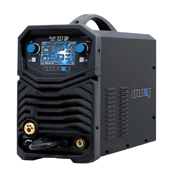
USER’S MANUAL Two types of connection can be used in TIG welding mode: generally, it is usually operated in Direct Current Straight Polarity (DCSP) – torch is connected with SK „–” and work piece with SK „+” . The second option is to use Direct Current Reverse Polarity (DCRP) – torch is connected with SK „+”... - Page 21 USER’S MANUAL Description of parameters on the LCD display Welding current Slow Feed Wire feed speed Wire diameter Welding voltage 2T/4T operating modes Fine adjustment of welding voltage Gas post-flow – shape of the front of the weld Plate thickness Welding material &...
- Page 22 USER’S MANUAL 3. The values of welding voltage and wire feeding speed are adjusted by rotating the right knob L4 . Because of the synergic di- gital programming, both the voltage and the wire speed will adjust together. The welding voltage is regulated independently by turning the left knob.
- Page 23 USER’S MANUAL Single pulse frequency is automatically ma- tched and adjusted (pulse frequency is pro- portional to current). When the wire feeding speed is less than 2.5m/min in single pulse mode,welder will enter COOL PULSE mode automatically. Welding material use in single pulse mode is suitable for cold pulse welding (COOL PULSE welding only appear under the single pulse mode).
- Page 24 USER’S MANUAL FUNCTIONAL INTERFACE – TIG Lift 1. Press the left button L3 to mode section. Select the TIG LIFT mode by left knob L2 and press the knob to confirm the selection. 2. When welding the display will change to show actual welding volts and amperage.
-
Page 25: Maintenance
10. TROUBLESHOOTING Not all problems with functioning of the device, are the evidence of failure. You can independently carry out an analysis in search of probable failure. In case of doubt, please contact to SPARTUS® dealer or authorized service center. - Page 26 USER’S MANUAL PROBLEMS WITH THE DEVICE Poorly connected to the supply voltage. After turning ON the switch the device does not respond. Failure of power switch. No power supply. No arc. A break in circuit welding. A break in the control circuit. Overheat protection is on.
- Page 27 A masterly combination of high quality production, excellent parameters and ergonomics – these are fea- tures of the SPARTUS® Master series of devices, which were created with demanding welding jobs in mind. Precision, functionality, excellent parameters and resistance to high workloads –...
- Page 28 Videopresentation of products Subscribe to the channel SPARTUS.INFO...
Need help?
Do you have a question about the EasyMIG 227DP and is the answer not in the manual?
Questions and answers