
Related Manuals for Leviton Mini Meter MMU MMT02


Summary of Contents for Leviton Mini Meter MMU MMT02
- Page 1 Mini Meter MMU (Multiple Meter Units) Cat. No. MMT02 Installation Manual PK-A3459-10-00-0A...
-
Page 3: Table Of Contents
TABLE OF CONTENTS Product Description ........................1 Electrical Specifications .......................2 Installation Instructions ........................6 4 What to do if ..........................15 Standard Statements and Warranty ................... 16... -
Page 4: Product Description
READ THESE INSTRUCTIONS BEFORE INSTALLING. 1.1 General Description The Leviton Mini Meter is a self-powered meter that is current transformer (CT) rated electronic kilowatt-hours (kWh). It is designed for permanent connection to an electrical service. Mini Meters come in dual-element (3-wire) configuration. This guide is for use with Mini Meter Multiple Meter Units (MMUs). -
Page 5: Electrical Specifications
Dinkle/International Connector 4.4 in-lb of torque maximum EK508-11P or Equivalent. Product approved for use with Leviton Current Transformers, rated at 200A. NOTE: Pollution Degree 2: Normally, only non-conductive pollution occurs. Occasionally, however, a temporary conductivity, caused by condensation, must be expected. - Page 6 2 ELECTRICAL SPECIFICATIONS 2.2 Input/Output Connections and User Display Sealing Post LCD Indicator Load Connection Specifications Voltage Inputs (wire connections) Description Black wire, voltage input, Line 1, 120V with respect to neutral White wire, Neutral input Red wire, voltage input, Line 2, 120V with respect to neutral CT Inputs CT1: X1 Current Transformer input, CT1.
- Page 7 While in a failure condition, in addition to displaying a “FAIL” code on the error screen, the screen ID (left-most digit) on every screen blinks, alternating between the screen ID and the character “F” . If the meter reports a failure condition, contact Leviton technical assistance at 1-800-824-3005 (USA Only) or 1-800-405-5320 (Canada Only).
- Page 8 2 ELECTRICAL SPECIFICATIONS CT Amperage Startup Screen, Screen 1: Real Energy, No Error Conditions No Error Conditions Error Screen Showing a Failure code, Error Screen Showing a Reverse Current Factory Service Required Installation Error on Line 1 Error Screen Showing a Power Factor Error Screen Showing a Low Voltage Installation Error on Line 2 Installation Error on Lines 1 and 2...
-
Page 9: Installation Instructions
• Line 1, Line 2, Line 3 (where appropriate) and Neutral hook-up wires as needed for the electrical service. Wires must be 18 AWG or larger and insulated for 300 VAC minimum. • Current Transformers (CTs): This product is designed for use with Leviton 100mA solid core (CDA02-xxx) or split core (CTD02-xxx) CTs. - Page 10 3 INSTALLATION INSTRUCTIONS 3.4 Mounting the Enclosure 3.4.1 Selecting a Mounting Location MMUs require a switch or circuit breaker as part of the building installation. The switch or circuit breaker must be marked as the disconnecting device for the MMU. It is recommended to mount the MMU near the disconnecting device in an area with adequate ventilation.
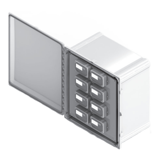
- Page 11 3 INSTALLATION INSTRUCTIONS 3.4.3 Mounting Procedure 1. Attach the mounting brackets to the back of the enclosure with the four provided screws as shown below. 2. Secure the enclosure with fasteners to the selected surface via mounting holes. 3. Verify that the enclosure is not loose and that all connections are secure. 4.
- Page 12 3 INSTALLATION INSTRUCTIONS 3.4.4 Conduit Installation WARNINGS: • To reduce risk of shock or electrocution, always open or disconnect the circuit from the power distribution system of a building before installing or servicing current transformers. • In accordance with NEC, CTs may not be installed in any panel board where they exceed 75% of the wiring space of any cross-sectional area.
- Page 13 3 INSTALLATION INSTRUCTIONS 3.5 Installation of Current Transformers WARNINGS: • TO AVOID FIRE, SHOCK OR DEATH, make sure service is disconnected before any connections are made. • Voltage connections must be made in accordance with NEC Section 240 and all other local electrical code requirements.
- Page 14 3 INSTALLATION INSTRUCTIONS Wiring the MMU LINE APT #1 APT #2 LOAD LOAD APT #3 APT #4 LOAD LOAD APT #5 APT #6 LOAD LOAD APT #7 APT #8 LOAD LOAD BREAKER PANEL APT #XX APT #XX Multiple Meter LOAD LOAD Unit Cabinet FUSE...
- Page 15 3 INSTALLATION INSTRUCTIONS LINE APT #1 APT #2 LOAD LOAD APT #1 APT #2 APT #3 APT #4 LOAD LOAD APT #3 APT #4 APT #5 APT #6 LOAD LOAD APT #5 APT #6 APT #7 APT #8 LOAD LOAD APT #7 APT #8 BREAKER...
- Page 16 3 INSTALLATION INSTRUCTIONS LINE APT #1 APT #2 Ø A Ø A LOAD LOAD APT #1 APT #2 Ø B Ø B APT #3 APT #4 Ø C Ø C LOAD LOAD APT #3 APT #4 Ø A Ø A APT #5 APT #6 Ø...
- Page 17 3 INSTALLATION INSTRUCTIONS 3.6 Testing the Installation Testing Voltage The meter LCD is active when the Mini Meter has a proper power supply. Test the voltage with an AC Voltmeter to verify that the voltage across voltage line terminals (L1 to Neutral and L2 to Neutral) does not exceed maximum voltage.
-
Page 18: What To Do If
• Verify that a load that draws more than 1 Amp is connected to the meter. Properly installed meters with sound connections and secure conduit fittings should not require user maintenance. If the meter is functioning abnormally, contact Leviton technical support at 1-800-824-3005 (USA Only) or 1-800-405-5320 (Canada Only). -
Page 19: Standard Statements And Warranty
LIMITED 5 YEAR WARRANTY AND EXCLUSIONS Leviton warrants to the original consumer purchaser and not for the benefit of anyone else that this product at the time of its sale by Leviton is free of defects in materials and workmanship under normal and proper use for five years from the purchase date. Leviton’s only obligation is to correct such defects by repair or replacement, at its option.
Need help?
Do you have a question about the Mini Meter MMU MMT02 and is the answer not in the manual?
Questions and answers