Advertisement
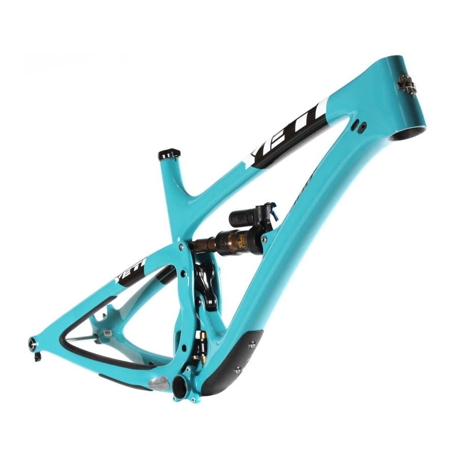
THE LOWDOWN ON THE SB6c AND ITS FEATURES
- SWITCH INFINITY TECHNOLOGY PATENTED SUSPENSION SYSTEM
- HIGH MODULUS CARBON FIBER MAIN FRAME AND SWING ARM
- OVERSIZED PIVOT PINS WITH ENDURO MAX BEARINGS
- INTEGRATED ISCG 05 MOUNTS
- TAPERED INSET HEAD TUBE (44MM/56MM)
- SUSPENSION BY FOX (8.5 X 2.5)
- CUSTOM CHAIN-SLAP GUARDS
- INTERNALLY ROUTED CABLES
- DIRECT MOUNT FOR SHIMANO SIDE SWING FRONT DERAILLEUR
- DEDICATED BOOST 12 X 148 DROPOUTS
- The SB6c delivers 6 inches (157mm) of travel with our patented Switch Infinity Technology. Efficient pedaling performance while still smooth and continuous when the going gets rough.
- High modulus carbon provides a stiff, strong and light weight chassis.
- Oversized pivot pins help create a stiff interface between the front and rear triangles of the frame. Custom Enduro Max sealed bearings keep things moving freely at the pivots.
- The ISCG 05' tab is built into your SB6c. The built in system is lighter than a conventional tab and allows for a full myriad of chainguide options.
- Using our inset head tube on the SB6c allows for a larger head tube with more area, increased stiffness, and lower overall ride height without compromising any performance.
- The SB6c uses a 2.5 inch stroke, 8.5 inch eye to eye Float-X shock, by Fox Racing Shox.
- Custom chain-slap guards on the seat stay and chain stay keep things quiet while riding and protect the frame.
- The SB6c features internal cable routing for clean protected cables and a very clean looking bike.
- The SB6c has a removable front derailleur mound specifically designed around the new Shimano side swing D-Type front derailleur.
- Dedicated Boost 12 x 148 dropouts for strength, stiffness and ease of wheel installation.
GEOMETRY

FOX 36 / 160MM FORK
| XS | SM | MD | LG | XL | |
| A | 15.0 | 16.5 | 17.5 | 19 | 20.5 |
| B | 21.8 | 22.8 | 23.8 | 24.8 | 25.8 |
| C | 65.5 | 65.5 | 65.5 | 65.5 | 65.5 |
| D | 73.5 | 73.5 | 73.5 | 73.5 | 73.5 |
| E | 17.4 | 17.4 | 17.4 | 17.4 | 17.4 |
| F | 44.6 | 45.7 | 46.8 | 47.8 | 48.9 |
| G | 13.6 | 13.6 | 13.6 | 13.6 | 13.6 |
| H | 28.7 | 28.8 | 28.9 | 28.9 | 28.9 |
| I | 3.7 | 4.3 | 4.8 | 5.6 | 6.3 |
| J | 21.6 | 21.6 | 21.6 | 21.6 | 21.6 |
| K | 1.73 | 1.73 | 1.73 | 1.73 | 1.73 |
| L | 22.6 | 23.2 | 23.6 | 24.4 | 25.0 |
| M | 15.1 | 15.9 | 16.8 | 17.6 | 18.3 |
FIT
| X-SMALL | 4'11" (145CM) - 5'3" (160CM) |
| SMALL | 5'3" (160 CM) - 5'7" (170 CM) |
| MEDIUM | 5'7" (170 CM) - 5'11" (180 CM) |
| LARGE | 5'11" (180 CM) - 6'3" (191 CM) |
| X-LARGE | 6'3" (191 CM) - 6'6" (198 CM) |
KEEP YOUR YETI FRESH AND CLEAN
OVERVIEW
Following these guidelines will help maintain the performance of your bicycle and prevent more serious problems from arising. It is important to remember that service intervals can vary depending on climate, trail conditions and riding frequency. If you are unsure about working on your own bicycle, contact your authorized Yeti Dealer or visit the repair help section at www.parktool.com for more information on general bicycle maintenance.
SCHEDULE
| WEEKLY | MONTHLY | 3 MONTHS | ANNUALLY | |||||
| CLEAN AND LUBE CHAIN | • | |||||||
| CHECK TIRE PRESSURE | • | |||||||
| CLEAN BIKE OF MUD AND DEBRIS | • | |||||||
| CHECK BRAKE FUNCTION | • | |||||||
| CHECK SHOCK PRESSURE, IF APPLICABLE | • | |||||||
| CHECK FOR LOOSE BOLTS AND TIGHTEN, IF NECESSARY | • | |||||||
| CHECK HEADSET AND TIGHTEN / LOOSEN, IF NECESSARY | • | |||||||
| THOROUGHLY CLEAN PIVOT POINTS WITH A RAG (DO NOT LUBRICATE) | • | |||||||
| LUBE INFINITY LINK EVERY 40 HRS. (YETI HEAVY MOLYBDENUM GREASE) | • | |||||||
| REPLACE BRAKE PADS, IF NECESSARY | • | |||||||
| CHECK TIRES FOR WEAR | • | |||||||
| CHECK SPOKE TENSION AND RETENTION, IF NECESSARY | • | |||||||
| CHECK CHAIN FOR WEAR AND REPLACE IF NECESSARY | • | |||||||
| COMPLETE TUNE-UP PERFORMED BY AN AUTHORIZED YETI DEALER | • | |||||||
TORQUE
Yeti strongly recommends using a torque wrench when assembling your frame. Torque specifications for individual parts on the SB6c are listed below, as well as in the step by step assembly instructions later in the manual. For general bicycle maintenance please consult the torque specifications of the manufacture's component you are adjusting.
KEY TORQUE SPECS
| PART NUMBER | DESCRIPTION | TORQUE (NM) |
| 300030151 | BOLT TI MALE M6X1X12MM | 7 |
| 300030057 | INFINITY LINK BOLTS | 12 |
| 300040454 | COLLET BOLT M8 | 8 |
| 300040480 | UPPER LINK COLLET AXLE | 3 |
| 300040478 | LOWER LINK AXLE | 13 |
| 300040479 | MAIN PIVOT COLLET AXLE | 3.5 |
SHOCK SETUP
YETI TIPS
Inspect your shock for any visible damage. If oil is leaking or you notice any damage to the surfaces or seals, please contact the Fox Racing Shox service center for repair at 800. FOX.SHOX or your local bike shop.
Shock set-up can fluctuate greatly based on the rider. The set-up guide is intended as a base line to get the rider started. Experiment with your settings to find the set-up that works best for you.
TOOLS NEEDED

- Shock Pump
- Metric Tape Measure
QUICK START GUIDE
| ADJUSTMENT | SETTING |
| AIR SPRING SETTING (PSI) | RIDER WEIGHT LESS 10 PSI |
| MEASURED SAG (MM) | 17-18MM |
| REBOUND | *5 CLICKS |
| TRAIL ADJUST | OPEN (DESCEND) |
*All clicks are counted clockwise, rotating from the all the way out or counter - clockwise dial position. Number of clicks of rebound will vary based on air pressure.
- AIR PRESSURE
The main air spring controls the sag of the shock. For the SB6c to ride properly it is important to setup the shock with the correct amount of sag. The SB6c works best with 18-19MM of measured sag. To increase the sag reduce the main spring air pressure. To reduce the sag increase the main spring air pressure. Cycle the shock 5-10 times to equalize the EVOL chamber before measuring sag.
![]()
- SAG
Once you have set your baseline air pressure you need to measure the sag. To measure the sag slide the travel indicator (O-Ring) up against the shock body. With a friend supporting the bike and with the shock in "open," sit on the saddle (do not bounce) and allow your body weight to compress the shock. Once you have compressed the shock, get off the bike and measure the distance between the shock body and the new position of the travel indicator (O-Ring). This is your sag.
![]()
- REBOUND AND COMPRESSION
The rebound has 14 clicks of adjustment. The rebound knob is the red adjustment dial located at the front of the air can. When the shock is mounted on the bike a small allen wrench is the best way to rotate it. Slower rebound- turn the knob clockwise, Faster rebound- turn the knob counter-clockwise. Compression is adjusted 2 ways. Low speed compression can be tuned for the "open" position with the black adjuster, giving the shock 3 positions. The Blue lever is a 3 position lever: Open, Medium and Firm. For our bikes, unless you are on pavement, we recommend using the "open" setting. The Switch Infinity design will do the rest!
![]()


DERAILLEUR HANGER INSTALL
YETI TIPS
NOTE: The hanger cap is REVERSE THREADED. Be careful not to strip out the Hanger tool faces. The cap is marked with a tighten direction arrow.
Inspect the frame around the hanger seat for any suspicious damage any time you replace a hanger, but especially if you are replacing it due to damage.

TOOLS NEEDED
- 6mm Allen key
- Grease
- HANGER SEAT
Lightly grease the outside surface of the hanger where it interfaces with the frame. The hanger will fit into its space on the inside of the swingarm and presses easily into the frame.
![]()
- HANGER CAP SEAT
Lightly grease the threasd on the hanger cap. The hanger cap REVERSE threads into the hanger from the outside of the swing arm. Hand thread the cap into the hanger.
![]()
- TIGHTENING
Using a 6mm allen key, tighten the hanger cap into the hanger. REMEMBER, it is REVERSE THREADED. Follow the "Tighten" arrow on the cap.
*Torque to 80 in/lbs (9Nm)
![]()
- COMPLETED
The installed hanger and cap should look like this, sitting flush against the frame on both the inside and outside of the swing arm. If the hanger or cap are not sitting flush against the frame, remove them and inspect the frame surfaces for debris as well as the threads for damage.
![]()


CABLE HOUSING SETUP
The SB6c uses internally routed full length cable housing. By using full cable housing, we have eliminated break points in the line of your shifter housing. This allows riders to experience better overall shifting performance by reducing the entrance of unwanted elements such as sweat and sediment. By routing that housing internally we add to the protection form the elements and clean up the lines of the bike. No more zip ties to snag your shorts on and no more loose housing rattling around on your paint.
Do not remove any of the housing guide tubes that are installed in your frame and swingarm. They will be used to pull your housing through the frame. If you are replacing housing, use the old housing to pull your new housing through the frame.
If you don't have the tubes or old housing as a guide you can fish for it, but it will be easier to get an internal routing tool.

The failure to properly route shifter housing can cause malfunction of the shift mechanism and unexpected shifting of gears.
REAR BRAKE AND DERAILLEUR ROUTING.
Your rear brake and shifter housing will run parallel around the left side of the head tube. From there you will run those two into the housing ports on the non drive side of the head tube. The Rear shift housing and brake housing exit the front triangle just above the Infinity Link. The brake exiting on the non drive side, the shift exiting on the drive side, both continuing into the coorispoding port on the swing arm.

- Use rubbiung alcohol to lubricate the housing. It will pass through the rubber grommets much easier.
- It may be easier in some cases to run the housing from the back of the bike up.
REAR BRAKE CONTINUED
The rear brake housing will exit the swing arm via the port on the chainstay and go from there directly to the brake caliper. If possible, adjust the housing/caliper angle to give the housing the cleanest, shortest route to the port.

REAR DERAILLEUR CONTINUED
The rear shift housing exits the swing arm on the top, just above the derailleur. Make sure you leave enough slack in the housing to allow for a smooth curve from the housing port to the derailleur.

DROPPER POST
The dropper post housing will exit the frame at the upper port on the drive side of the head tube. It is best to run the housing from the seatpost up using either the guide provided with a new frame or the previous housing. Without a guide, it can be difficult to fish the housing into the downtube, but it is possible.

FRAME ASSEMBLY
YETI TIPS
Make sure your tools are in good condition. A worn allen key can round the hex on a bolt not allowing for proper torque.
Torque settings are listed throughout the instructions. It is also import to prep all bolt threads. The instructions denote whether to use a Loctite compound or grease.

Service on Yeti bicycles requires special knowledge and tools. Yeti Cycles recommends that all service and repairs be performed by an authorized Yeti Dealer
TOOLS NEEDED

- Dead blow hammer
- 2.5mm allen key
- Two - 5mm allen keys
- Two - 6mm allen keys
- 10mm allen key
- Guide pin tool
- Lock ring pliers
- Grease
- Blue (248) Loctite
- Pink (222) Loctite
- Torque wrench
- All the parts you'll need to get your SB6c put together.
![]()
- Slip washers onto and apply blue (248) Loctite to the 4 bolts that secure the Switch Infinity Link to the frame. Insert them into their place and hang the black Infinity link fitting washers from them. Place them with the flat side toward the opening.
![]()
- Insert the Infinity Link from the non-drive side. The Infinity logo should be up and the Fox logos facing the non-drive side. Rock the link into place capturing the black fitting washers. Make sure that they have not slipped or rotated. The flat end of the fitting washers must be facing the opening in the frame.
![]()
- While holding the link in place lightly tighten the bolts. You want them to snug so that the link does not move and so that the fitting washers are fully captured, but don't try to torque them by hand! Finish the job with a torque wrench.
Torque to 12 Nm
![]()
- Insert the link and align the lower pivot. Place the steel washer over the pivot pin, apply a small amount of grease, and using a Fox Guide Pin to align the bearing spacer insert the pivot pin. Use a soft mallet to tap it through if needed.
![]()
- Place the steel washer on the lower link bolt and apply pink Loctite (222).
![]()
- Using two 5mm allen wrenches tighten the lower link pivot pin. Use a properly calibrated torque wrench to finish the job.
Torque to 13 Nm
![]()
- Slide the swingarm into place over the Switch Infinity Link and align the main pivot. Apply a small amount of grease to the un-threaded part of the main pivot pin. Apply pink Loctite (222) to the threads.
![]()
- Slide the main pivot pin through the swingarm and Infinity Link using a Fox Guide Pin to align the bearing spacer. Use a soft mallet to help if needed. Lightly thread the pivot pin into the swingarm using a 10mm allen wrench. Do not torque yet.
![]()
- Prepare and install the upper link pivot pin the same way you install the main pivot pin. Use the Fox Guide pin to align the bearing spacer as you slide it through the link. Again, do not torque yet!
![]()
- Using Fox Guide Pins, install the rear shock as shown. Insert the guide pins from the drive side.
![]()
- Lightly grease the shock mounting hardware, install the appropriate washer and place the female sleeve over the Fox Guide Pin.
![]()
- Using a soft mallet push the female shock mounting hardware through the frame and shock on the Fox Guide Pins.
![]()
- Prep and install the male shock mounting hardware on both ends of the shock. Apply Blue Loctite (248) to the threads and install the washer. Thread the bolt in snug, but do not torque.
![]()
- Time to get the torque wrench out. Using a 5mm allen on one side and your properly calibrated torque wrench on the other torque the shock mounting hardware on both ends of the shock.
Torque to 7 Nm
![]()
- Using a 10mm allen wrench finish tightening the main pivot axle and the upper link axle. Torque the pivot axles using a properly calibrated torque wrench.
Torque to 3.5 Nm
![]()
- Prepare both your collet bolts with grease. You want to have grease on the threads and on the collet wedge.
![]()
- Using a 5mm allen wrench, thread both collet bolts into the pivot axles. Finish tightening using a properly calibrated torque wrench.
Torque to 8 Nm
![]()


FRAME ASSEMBLY IS COMPLETE. NOW GET YOUR PARTS ON THERE AND GO FOR A RIDE!
EXPLODED VIEW

EXPLODED VIEW PARTS LIST
| ITEM# | PART # | DESCRIPTION | QTY |
| 1 | N/A | SB6C FRONT TRIANGLE | 1 |
| 2 | 300070006 | ICE AXE HEAD BADGE | 1 |
| 3 | 300060072 | YETI SEAT CLAMP | 1 |
| 4 | 400100119 | SB6C DOWN TUBE PROTECTOR | 1 |
| 5 | 300030148 | WASHER 5.1 X 8.9 X 1MM | 2 |
| 6 | 300030010 | BOLT-CAP H20 (M5 X 0.8 X 16MM) | 2 |
| 7 | 300040474 | GROMMET BLANK | 2 |
| 8 | 300040475 | GROMMET 5MM | 2 |
| 9 | N/A | SB6C SWINGARM | 1 |
| 10* | 300060073 | 12X148 HANGER (2016 NOT PICTURED) | 1 |
| 10* | 300060070 | 12X142 HANGER STD KIT GEN2 (2015) | 1 |
| 11 | 300040476 | SB6C FD DIRECT MOUNT | 1 |
| 12 | 400100120 | SB6C CS/SS PROTECTOR | 1 |
| 13 | 400100121 | SB6C CHAINDUCK GUARD | 1 |
| 14 | 400100122 | SB6C CS LOWER PROTECTOR | 1 |
| 15 | 200020201 | FOX LINEAR BEARING ASSEMBLY | 1 |
| 16 | N/A | FOX FLOAT-X 8.5 X 2.5 | 1 |
| 17 | 214-09-006 | FOX MOUNT KIT 21.84MM (22MM) | 1 |
| 18 | 214-09-035 | FOX MOUNT KIT 44.856MM (45MM) | 1 |
| 19 | 300040478 | AXLE 15MM X 36.0, M10 X 1.5 THREAD | 1 |
| 20 | 300030280 | CAP AXLE 15MM, M10 X 1.5 THREAD | 1 |
| 21 | 300030151 | BOLT TI MALE M6 X 12.0MM | 3 |
| 22 | 300030288 | BOLT TI STUD 8.0 X 54.0MM | 1 |
| 23 | 300030262 | BOLT TI FEMALE 8.0 X 31.0MM GEN2 | 1 |
| 24 | 300030062 | WASHER 6.5 X 12.5 X 0.5 MM | 2 |
| 25 | 300030069 | WASHER 8.8 X 12.5 X 0.5 MM | 2 |
| 26 | 300040479 | COLLET AXLE 15 X 52.0S X 9.75T M15X1.5 | 1 |
| 27 | 300040480 | COLLET AXLE 15 X 55.5S X 14.0T M15X1.5 | 1 |
| 28 | 300040454 | COLLET WEDGE ASSEMBLY GEN2 | 2 |
| 29 | 300030057 | BOLT CAP M6 X 1 X 20MM | 4 |
| 30 | 300030214 | WASHER 10 X 6.2 X 1MM | 4 |
| 31 | 300030276 | WASHER 15.2 X 21.5 X 1MM | 1 |
| 32 | 300030277 | WASHER 10.4 X 21.5 X 1MM | 1 |
| 33 | 300040477 | SB6C LINK | 1 |
| 34 | 300030248 | SPACER 15MM X 25.75MM | 1 |
| 35 | 300030278 | SPACER 15MM X 6.75MM | 1 |
| 36 | 300020045 | BEARING F6902-2RS-MAX 28X15X7_2.5 OUT | 4 |
REBUILD KITS
| PART # | DESCRIPTION | QTY |
| 200020232 | SB6C MASTER REBUILD KIT | |
| 300020045 | BEARING F6902 2RS 28X15X7 OUT | 6 |
| 300030057 | BOLT CAP M6X1X20 | 4 |
| 300030062 | WASHER SS 6.5MM ID 12.5 OD.5M | 2 |
| 300030069 | WASHER SS 8.8MM ID 12.5MM OD. | 2 |
| 300030151 | BOLT-TI-MALE M6X12MM | 3 |
| 300030154 | STUD-TI-FEMALE 8X54.5MM | 1 |
| 300030214 | WASHER 10 X 6.2 X 1 | 4 |
| 300030248 | SPACER 15X25.75MM | 1 |
| 300030249 | BOLT-TI-FEMALE 8.0OD M6X31.5M | 1 |
| 300030276 | WASHER 15.2X21.5X1 | 1 |
| 300030277 | WASHER 10.4X21.5X1 | 1 |
| 300030278 | SPACER 15X6.75MM | 1 |
| 300030279 | FLAT HEAD M5X.8X10 | 2 |
| 300030280 | CAP AXLE M10X1.5X15 GEN2 | 1 |
| 300040454 | COLLET-WEDGE ASSEMBLY GEN2 | 2 |
| 300040474 | PORT GROMMET BLANK | 5 |
| 300040475 | PORT GROMMET 5MM | 4 |
| 300040476 | FD DIRECT MOUNT REMOVABLE | 1 |
| 300040478 | AXLE 15MM X 36.0 M10X1.5 GEN2 | 1 |
| 300040479 | AXLE COLLET 15X52.0SX9.75T | 1 |
| 300040480 | AXLE COLLET 15X55.5SX14.0T | 1 |
| 200020232 | SB6C BEARING KIT | |
| 300020045 | BEARING F6902 2RS 28X15X7 OUT | 6 |
| 200020233 | SB6C HARDWARE KIT | |
| 300030057 | BOLT CAP M6X1X20 | 4 |
| 300030062 | WASHER SS 6.5MM ID 12.5 OD.5M | 2 |
| 300030069 | WASHER SS 8.8MM ID 12.5MM OD. | 2 |
| 300030151 | BOLT-TI-MALE M6X12MM | 3 |
| 300030154 | STUD-TI-FEMALE 8X54.5MM | 1 |
| 300030214 | WASHER 10 X 6.2 X 1 | 4 |
| 300030249 | BOLT-TI-FEMALE 8.0OD M6X31.5M | 1 |
| 300030276 | WASHER 15.2X21.5X1 | 1 |
| 300030277 | WASHER 10.4X21.5X1 | 1 |
| 300030278 | SPACER 15X6.75MM | 1 |
| 300030279 | FLAT HEAD M5X.8X10 | 2 |
| 300030280 | CAP AXLE M10X1.5X15 GEN2 | 1 |
| 300040454 | COLLET-WEDGE ASSEMBLY GEN2 | 2 |
| 300040474 | PORT GROMMET BLANK | 5 |
| 300040475 | PORT GROMMET 5MM | 4 |
| 300040476 | FD DIRECT MOUNT REMOVABLE | 1 |
| 300040478 | AXLE 15MM X 36.0 M10X1.5 GEN2 | 1 |
| 300040479 | AXLE COLLET 15X52.0SX9.75T | 1 |
| 300040480 | AXLE COLLET 15X55.5SX14.0T | 1 |
| 200020237 | SB6-C FRONT DERAILLEUR MOUNT KIT | |
| 300030279 | FLAT HEAD M5X.8X10 | 2 |
| 300040476 | FD DIRECT MOUNT REMOVABLE | 1 |
| 200020234 | FOX LINEAR BEARING 74.0MM SB6 | |
| 200020201 | FOX LINEAR BEARING 74.0MM ASSE | 1 |
| 300030057 | BOLT CAP M6X1X20 | 4 |
| 300030214 | WASHER 10 X 6.2 X 1 | 4 |
| 400100126 | SB6C PROTECTOR KIT | |
| 400100119 | PROTECTOR SB6-C DT | 1 |
| 400100120 | PROTECTOR SB6-C CS/SS | 1 |
| 400100121 | PROTECTOR SB6-C CHAIN SUCK | 1 |
| 400100122 | PROTECTOR SB6-C CS LOWER | 1 |
| 200020236 | SB6-C CABLE GUIDE KIT 2014- | |
| 300040474 | PORT GROMMET BLANK | 5 |
| 300040475 | PORT GROMMET 5MM | 4 |
YETI CYCLES
621 Corporate Circle, Unit B
Golden, CO 80401
(p) 303-278-6909
(f) 303-278-6906
www.yeticycles.com
BUSINESS HOURS
Monday-Friday
8AM-11:30AM, 1:00PM-5:30PM
(Mountain Time)
Documents / Resources
References
Download manual
Here you can download full pdf version of manual, it may contain additional safety instructions, warranty information, FCC rules, etc.
Advertisement


Need help?
Do you have a question about the SB6C and is the answer not in the manual?
Questions and answers