Advertisement
INTRODUCTION
This model specific manual is designed to be used in conjunction with the general Yeti Owner's Manual and the manuals supplied by the suspension manufactures. If you did not receive the Yeti owner's manual or the manual provided by the suspension manufacturer download the materials off the Internet, or contact your local dealer.
Bicycling can be a hazardous activity even under the best of circumstances. Proper maintenance of your bicycle is your responsibility and when done properly helps reduce the risk of injury and damage to your bicycle.
This manual outlines basic setup and maintenance recommendations of your new Yeti. Because it is impossible to anticipate every situation or condition that may occur during the assembly, setup, and maintenance of your bicycle, Yeti recommends that all service and repairs be performed by your local authorized Yeti Dealer.
This manual contains many "Warnings" and "Cautions" concerning the consequences of failure to maintain or inspect your bicycle. The word "Warning" indicates a potentially hazardous situation in which, if not avoided, could result in serious injury or death. The word "Caution" indicates a potentially hazardous situation in which, if not avoided may result in minor injuries or damage to your bicycle or a component of your bicycle. Be sure to read and understand all of the Warnings and Cautions listed in the manual.

Make sure you review and understand the warnings, instructions, and content of this manual and accompanying manuals for your bicycle.
Technological advances have made bicycles and bicycle components more complex and the pace of innovation is increasing. It is impossible for this manual or the accompanying manuals to provide all the information required to properly repair and/or maintain your bicycle. In order to help minimize the chances of an injury, it is critical for you to have work performed by an authorized Yeti retailer.
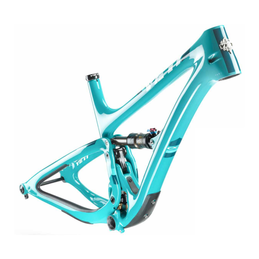
THE LOWDOWN ON THE SB5 AND ITS FEATURES
- SWITCH INFINITY TECHNOLOGY PATENTED SUSPENSION SYSTEM
- TURQ AND CARBON SERIES FRAMES
- COLLET AXLE SYSTEM ON PIVOTS REDUCES BEARING WEAR
- OPTIMIZED FOR 1X DRIVETRAINS ONLY
- ISCG 05 CHAINGUIDE MOUNTS
- TAPERED INSET HEAD TUBE (44MM/56MM)
- SUSPENSION BY FOX (50MM X 210MM)
- CUSTOM DEBRIS AND CHAIN SLAP GUARDS
- INTERNALLY MOLDED CARBON CABLE ROUTING TUBES
- INTEGRATED AXLE AND DERAILLEUR HANGER SYSTEM
- INDUSTRY LEADING LOW STAND OVER
- The SB5 delivers 5 inches (127mm) of travel with our patented Switch Infinity Technology. Efficient pedaling performance while still smooth and continuous when the going gets rough.
- Top of the top Turq Series frames and our Carbon series both offer the same geometry and efficiency in all models.
- Colleсted pivot axles help create a stiff interface between the front and rear triangles. Custom Enduro Max sealed bearings keep things moving freely at the pivots.
- The SB5 does away with the front derailleur mount, making it a 1x drive specific frame. This increases stiffness in the frame, making the SB5 one of the stiffest bikes in our lineup.
- ISCG 05 chain guide mounts are included on the SB5 in case you want to go for some extra drivetrain security for the rowdy sections.
- Using our inset head tube on the SB5 allows for a larger head tube with more area, increased stiffness, and lower overall ride height without compromising any performance.
- The SB5 uses a 50mm stroke, 210mm eye to eye Float EVOL shock or DPX2 shock (Lunch Ride build), by Fox Racing Shox.
- Custom guards on the seat stay, chain stay and down tube keep things quiet while riding and protect the frame.
- The SB5 features internally molded routing tubes for all cables, making the bike quiet and clean looking as well as reducing maintenance and cable rub.
- Dedicated 12 x 148 Boost dropouts and integrated hanger with axle threads for strength, stiffness, ease of hanger and wheel installation.
- An already low stand over is made even lower in our small and extra small SB5 frames, giving them the lowest stand over clearance in the trail bike world.
GEOMETRY

FOX 34 / 150MM FORK

*All measurements are in millimeters
FIT
X-SMALL: 4'11" (150 CM) - 5'3" (160 CM)
SMALL: 5'3" (160 CM) - 5'7" (170 CM)
MEDIUM: 5'7" (170 CM) - 5'11" (180 CM)
LARGE: 5'11" (180 CM) - 6'3" (191 CM)
X-LARGE: 6'1" (185 CM) - 6'6" (198 CM)
MAINTENANCE
KEEP YOUR YETI FRESH AND CLEAN
OVERVIEW
Following these guidelines will help maintain the performance of your bicycle and prevent more serious problems from arising. It is important to remember that service intervals can vary depending on climate, trail conditions and riding frequency. If you are unsure about working on your own bicycle, contact your authorized Yeti Dealer for more information on general bicycle maintenance.
SCHEDULE

TORQUE
Yeti strongly recommends using a torque wrench when assembling your frame. Torque specifications for individual parts on the SB5 are listed below, as well as in the step by step assembly instructions later in the manual. For general bicycle maintenance please consult the torque specifications of the component you are adjusting.
KEY TORQUE SPECS
| PART NUMBER | DESCRIPTION | TORQUE (NM) |
| 300030151 | BOLT TI MALE (M6 X 1 X 12MM) | 7 |
| 300030057 | INFINITY LINK BOLTS (M6 X 1) | 12 |
| 300040484 | UPPER LINK COLLET AXLE (M10 X 10) | 3 |
| 300040486 | UPPER LINK COLLET WEDGE (M5 X.8) | 8 |
| 300040483 | LOWER LINK COLLET AXLE (M10 X 10) | 3 |
| 300040486 | LOWER LINK COLLET WEDGE (M5 X.8) | 8 |
| 300040485 | MAIN PIVOT COLLET AXLE (M15 X 1.5) | 3.5 |
| 300040454 | MAIN PIVOT COLLET WEDGE (M8 X 1.25) | 14 |
SHOCK SETUP
YETI TIPS
Inspect your shock for any visible damage. If oil is leaking or you notice any damage to the surfaces or seals, please contact the Fox Racing Shox service center for repair at 800. FOX.SHOX or your local bike shop.
Shock set-up can fluctuate greatly based on the rider. The set-up guide is intended as a base line to get the rider started. Experiment with your settings to find the set-up that works best for you.
We recommend starting out with 30% sag, which is 15mm of shock stroke. Your total shock stroke is 51mm's.
TOOLS NEEDED
- Shock Pump
- Metric Tape Measur
![]()

QUICK START GUIDE
| ADJUSTMENT | SETTING |
| BASELINE AIR SPRING SETTING | RIDER WEIGHT -10 LBS |
| MEASURED SAG (MM) | 15MM |
| REBOUND | 5-7 CLICKS* |
| COMPRESSION ADJUSTMENT | OPEN |
*All clicks are counted counter-clockwise, rotating from the all the way "in" or clockwise dial position.
- AIR PRESSURE
The main air spring controls sag. For the SB5 to ride properly it is important to setup the shock with the correct amount of sag. The SB5 works best with 15MM of measured sag. To increase sag, reduce the main spring air pressure. To reduce sag, increase the main spring air pressure. Always cycle the shock at least 10 times after any pressure adjustment to equalize the EVOL chamber before measuring sag.
![]()
- SAG
Once you have set your baseline air pressure and cycled the shock you are ready to measure the sag. To measure the sag slide the travel indicator (O-Ring) up against the shock body. With a friend supporting the bike and with the compression set "open," sit on the saddle and allow your body weight to compress the shock. Once you have compressed the shock, get off the bike and measure the distance between the shock body and the new position of the travel indicator (O-Ring). This is your sag.
![]()
- REBOUND
Rebound is adjusted using the red knob located by the front shock mount. Clockwise will slow the rebound, counter clockwise will speed it up. Rebound needs to be tuned to rider preference and air spring pressure. Too slow and the bike will feel like it is not ready for the next bump. Too fast and it will feel like the bike is bucking you off after an impact.
![]()
- COMPRESSION
Low-speed compression is adjusted in the "open" position using the black tabs and has 3 positions. 1 is wide open, 3 is more firm. This adjustment is subtle.
The blue lever has 3 positions: Open, Medium and Firm. For our bikes, unless you are on pavement on the way to the trail, we recommend using the "open" setting. The Switch Infinity design will do the rest!
![]()


DPX2 SHOCK SETUP
(FOR LUNCH RIDE KIT)
TOOLS NEEDED
- Shock Pump
- Metric Tape Measure
- 2.5 mm Allen wrench
![]()

QUICK START GUIDE
| ADJUSTMENT | SETTING |
| BASELINE AIR SPRING SETTING | RIDER WEIGHT -10 LBS |
| MEASURED SAG (MM) | 16MM |
| REBOUND | 5-7 CLICKS* |
| HIGH SPEED COMPRESSION | OPEN |
| LOW SPEED COMPRESSION | 8-9 CLICKS* |
*All clicks are counted counter-clockwise, rotating from the all the way "in" or clockwise dial position.
- AIR PRESSURE
The main air spring controls sag. For the SB5 LR to ride properly it is important to setup the shock with the correct amount of sag. To increase sag, reduce the main spring air pressure. To reduce sag, increase the main spring air pressure. Always cycle the shock at least 10 times after any pressure adjustment to equalize the EVOL chamber before measuring sag.
![]()
- SAG
The SB5 LR works best with 16MM of measured sag. To measure the sag slide the travel indicator (O-Ring) up against the shock body. With a friend supporting the bike and with the compression set "open," sit on the saddle and allow your body weight to compress the shock. Once you have compressed the shock, get off the bike and measure the distance between the shock body and the new position of the travel indicator (O-Ring). This is your sag.
![]()
- REBOUND
Rebound is adjusted using the red knob located on the drive side. Clockwise will slow the rebound, counter clockwise will speed it up. Rebound needs to be tuned to rider preference and air spring pressure. This may take some experimentation to dial in. Too slow and the bike will feel like it is not ready for the next bump. Too fast and it will feel like the bike is bucking you off after an impact.
![]()
- COMPRESSION
The blue lever on the non drive side has 3 positions: Open, Medium and Firm. For our bikes, unless you are on pavement on the way to the trail, we recommend using the "open" setting. The Switch Infinity design will do the rest!
Low-speed compression is adjusted using a 2.5mm allen wrench. It is located in the center of the blue 3-position lever. There are 10 clicks on this adjustment. This adjustment only effects the the "open" position.
![]()


DERAILLEUR HANGER INSTALL
YETI TIPS
 NOTE: The hanger cap is REVERSE THREADED. Be careful not to strip out the Hanger tool faces. The cap is marked with a tighten direction arrow.
Inspect the frame around the hanger seat for any suspicious damage to the carbon any time you replace a derailleur hanger, especially if you are replacing the hanger due to damage to the hanger.
TOOLS NEEDED
- 6mm Allen key
- Grease


- HANGER PREP
Lightly grease the threads and outside surface of the hanger and cap where it interfaces with the frame. The hanger will fit into its space on the inside of the swing arm and should press easily into the frame.
![]()
- HANGER CAP SEAT
Place the hanger into the recess on the inside of the swing arm. Thread the hanger cap into the hanger. The hanger cap REVERSE threads into the hanger from the outside of the swing arm. Start threading the cap by hand.
![]()
- TIGHTENING
Using a 6mm allen key, tighten the hanger cap into the hanger. REMEMBER, it is REVERSE THREADED. Follow the "Tighten" arrow on the cap. Finish tightening with a torque wrench if available.
![]()
*Torque to 80 in/lbs (9Nm)


CABLE SETUP
The SB5 uses internal molded tubing to make cable threading a cinch! No more rattling cable housing in your frame and no more fishing for cables required. Simply thread your housing through the correct port and you are done.
Follow these simple instructions to get each housing in the right place.

The failure to properly route housing can cause malfunction of the mechanism that could result in injury.
REAR BRAKE AND DERAILLEUR

Your rear brake and shifter housing should run parallel around the left side of the head tube. Run the shifter housing and the brake housing into the individual ports at the head tube. The brake housing will exit on the non-drive side port just in front of the Infinity Link. The shift housing comes out of the port on the drive side.
Both housings will enter the swing arm directly as shown above on the right.
REAR DERAILLEUR CONTINUED

The rear derailleur housing will exit the swing arm via the port on the side of the seat stay right in front of the rear derailleur. Create a gentle curve to the derailleur and adjust to the manufacturers specifications.
REAR BRAKE CONTINUED

The rear brake housing exits the swing arm on the inside of the chain stay and goes directly up to the caliper. If your caliper allows, adjust the housing attachment angle to reduce the bend in the cable as much as possible.
INTERNALLY ROUTED SEAT POST

The SB5 is designed to use an internally routed dropper post. The cover on the top of the down tube right in front of the seat tube/down tube junction reveals the final routing for the seat post. Remove the cover using a 2.5mm allen wrench. This will expose the channel the dropper housing passes through. Thread your housing from the head tube down into that channel. Guide the housing through the channel and out the other end and into the seat tube. Once you have the seat post installed and adjusted correctly, reinstall the cover.
FRAME ASSEMBLY
YETI TIPS
Make sure your tools are in good condition. A worn allen key can round the hex on a bolt not allowing for proper torque. Torque settings are listed throughout the instructions of this manual. It is important to prep all bolt threads. The instructions denote whether to use a Loctite compound or grease.
Service on Yeti bicycles requires special knowledge and tools. Yeti Cycles recommends that all service and repairs be performed by an authorized Yeti Dealer
TOOLS NEEDED
- 2.5mm allen key
- 5mm allen keys
- 4mm allen keys
- 10mm allen key
- Guide pin tool (Or two)
- Torque wrench
- Grease
- Blue (242) Loctite
![]()

- All the parts you'll need to get your SB5 frame assembled. Please refer to the exploded view later in this manual for more information.
![]()
- Slip washers (300030214) onto and apply blue (242) Loctite to the 4 bolts (300030057) that secure the Switch Infinity Link to the frame.
![]()
- Insert the bolts with washers on them into the frame and hang the black Infinity Link spacers from them. Orient them so that the flat surfaces are facing the opening in the frame where the Infinity link will go.
![]()
- Rock the Infinity Link into place capturing the black spacers against the frame. Be sure that the spacers do not rotate when you are installing the link. Hold the link in place by hand and thread the bolts into the link.
![]()
- Using a torque wrench, finish tightening the Infinity Link bolts using a crossing pattern.
*Torque to 12 Nm
![]()
- Lightly grease the bearing surfaces on your link (200020261).
![]()
- Place the spacing washers (300020049) on the lower (narrow) end of the link. The grease should help hold them in place.
![]()
- Insert the link into the frame and insert the lower link axle (300040483) to hold it all in place. Despite the picture, apply grease to the threads and shaft of the pivot axle. No Loctite needed.
![]()
- Insert the collet axle nut (300030287) in the corresponding keyed hole and thread the axle in using a 5mm allen wrench. The axle acts like a headset and is meant to preload the bearings.
*Torque: 3 Nm
![]()
- Install the lower link collet wedge. (300040486) Grease the threads and the wedge. Tighten with a 4mm allen wrench and finish with a torque wrench.
*Torque: 8 Nm
![]()
- Grease the threads and shaft of the main pivot axle. (300040485)
![]()
- Slide the swing arm into place, aligning the main pivot. Push the main pivot axle through the swing arm and Infinity Link from the non-drive side.
![warning]() NOTE: You may want to use a guide pin (200020118) to assist in aligning the sleeve in the Infinity link.
NOTE: You may want to use a guide pin (200020118) to assist in aligning the sleeve in the Infinity link.
![]()
- With the main pivot axle in place, grab the main pivot axle nut (300030285) and install it in the keyed recess on the drive side of the swing arm.
![]()
- Thread the main pivot axle into the main pivot axle nut using a 10mm allen wrench. Lightly tighten by hand and finish with a torque wrench.
*Torque to 3.5 Nm
![]()
- Place the spacing washers (300020049) on the bearings on the upper bearings of the link. The light film of grease will hold them in place.
![]()
- Slide the link into the swing arm, aligning the upper link pivot. You may need to rotate the swing arm or move the Infinity Link up or down to get the pivot to align.
![]()
- Grease the upper link pivot pin (300040484) and push it through the swing arm and link from the non-drive side.
![warning]() NOTE: You may want to use a guide pin (200020118) to assist in aligning the sleeve in the link.
NOTE: You may want to use a guide pin (200020118) to assist in aligning the sleeve in the link.
![]()
- With the upper link pivot axle in place, grab the upper link pivot axle nut (300030286) and push it into the keyed recess on the drive-side of the swing arm. Using a 5mm allen wrench, lightly tighten the axle. Finish with a torque wrench.
*Torque to 3 Nm
![]()
- Returning to the main pivot. Grease the threads and collet wedge of the main pivot collet wedge bolt (300040454) and thread it into the main pivot collet axle.
![]()
- Tighten firmly by hand and finish with a torque wrench.
*Torque to 14 Nm
![]()
- Grease the threads and collet wedge on the upper link collet bolt (300040486) and thread it into the upper link pivot collet axle with a 4mm allen wrench. Firmly tighten by hand and finish with a torque wrench.
*Torque to 8 Nm
![]()
- Slide the shock into place in the frame. Align the front shock mount using a guide pin (200020118) first.
![]()
- With the front mount guide pin in place, align rear shock mount with a second guide pin. NOTE: If a second guide pin is not available simply install the front mount hardware (see steps 24 and 25) and re use the guide pin in rear shock mount.
![]()
- Place a 8.5mm x 12.5mm washer (300030069) over the front shock mounting pin (300030153) and slide the mounting pin over the blunt end of the guide pin, pushing it through the frame.
![]()
- Place the 6.5mm x 12.5 washer (300030062) over a Male Ti bolt (300030151). Apply Blue Loctite to the threads. Using two 5mm allen wrenches tighten the male bolt into the shock mounting pin. Finish using a torque wrench.
*Torque to 7 Nm
![]()
- Thread a Male Ti bolt (300030151) into the rear shock mounting pin (300030289) and thread all the way in. Place a 8.5mm x 12.5mm washer (300030069) over the shock mounting pin assembly and slide it through the swing arm and shock using the blunt end of the guide pin to guide it through.
![]()
- Place the 6.5mm x 12.5 washer (300030062) over a Male Ti bolt (300030151). Apply Blue Loctite to the threads. Using two 5mm allen wrenches tighten the male bolt into the shock mounting pin assembly. Finish using a torque wrench.
*Torque to 7 Nm
![]()


FRAME ASSEMBLY IS COMPLETE.

EXPLODED VIEW

EXPLODED VIEW PARTS LIST


REBUILD KITS


CONTACTS
YETI CYCLES
621 Corporate Circle, Unit B
Golden, CO 80401
(p) 303-278-6909
(f) 303-278-6906
BUSINESS HOURS
Monday-Friday 8AM-11:30AM, 1:00PM-5:30PM
(Mountain Time)
Documents / Resources
References
Download manual
Here you can download full pdf version of manual, it may contain additional safety instructions, warranty information, FCC rules, etc.
Advertisement


Need help?
Do you have a question about the SB5 and is the answer not in the manual?
Questions and answers