Table of Contents
Advertisement
Quick Links
AUHMI-1XXA Series
10.1", 15.6", 21.5" Fanless Aluminum Die Casting Display
User Manual
Release Date
Revision
Sep. 2023
V1.0
®2023 Aplex Technology, Inc.
All Rights Reserved.
Published in Taiwan
Aplex Technology, Inc.
15F-1, No.186, Jian Yi Road, Zhonghe District, New Taipei City 235, Taiwan
URL:
http://www.aplex.com
Tel: 886-2-82262881
Fax: 886-2-82262883
Email:
aplex@aplex.com
0
AUHMI-1XXA Series User Manual
Advertisement
Table of Contents

Related Manuals for Aplex AUHMI-1 A Series


Summary of Contents for Aplex AUHMI-1 A Series
- Page 1 10.1”, 15.6”, 21.5” Fanless Aluminum Die Casting Display User Manual Release Date Revision Sep. 2023 V1.0 ®2023 Aplex Technology, Inc. All Rights Reserved. Published in Taiwan Aplex Technology, Inc. 15F-1, No.186, Jian Yi Road, Zhonghe District, New Taipei City 235, Taiwan URL: http://www.aplex.com...
- Page 2 Revision History Reversion Date Description 2023/09/01 Official Version AUHMI-1XXA Series User Manual...
-
Page 3: Revision History
This information in this document is subject to change without notice. In no event shall Aplex Technology Inc. be liable for damages of any kind, whether incidental or consequential, arising from either the use or misuse of information in this document or in any related materials. -
Page 4: Table Of Contents
Table of Contents Revision History………………………………………………………………………………….1 Warning!………………………………………………………………………………….……..….2 Disclaimer……………………….……………………………………………….…………………2 Chapter 1 Getting Started 1.1 Features…………………………………………………..…………………………….4 1.2 Specifications…………………………………………………………..…….………4 1.3 Dimensions……………………...……………...…..…………………….…….…7 1.4 Brief Description of AUHMI-1XXA Series……..…………………….10 1.5 VESA Mounting………………………………………..…………………….13 1.6 Panel Mount……..………………………………………………………….14 1.7 Cable Cover……..…………………………………………………………….16 Chapter 2 Hardware 2.1 AD Board Specifications………….…...………..….…..……………….….18 2.2 AD Board Diemensions……………..…………….…………………….……19 2.3 Jumpers and Connectors Location…..…….…………………………...20 2.4 Jumpers and Connectors…..……………….….…………………………...21 Chapter 3... - Page 5 Figure 1.12: AUHMI-110AP/R(H) Panel Mount……………..………………..14 Figure 1.13: AUHMI-116AP/R(H)_AUHMI-121AP/R(H)Panel Mount….15 Figure 1.14: AUHMI-116AP/R(H)_AUHMI-121AP/R(H)Cable Cover……17 Figure 2.1: Dimensions of TB-6030………………….…..………………..19 AUHMI-1XXA Series User Manual...
-
Page 6: Getting Started
Chapter 1 Getting Started 1.1 Features ⚫ 10.1”/15.6”/21.5” Fanless Aluminum Diecasting display ⚫ Gap-free sealing and Slim Front Frame architecture ⚫ IP66 Front Panel with Anti-Corrosion Enclosure ⚫ 24V DC power input 1.2 Specifications AUHMI-1XXA Series I/O port LVDS 1 x 18/24 bit dual Channel on board VIDEO 1 x VGA/ 1 x HDMI/ 1 x DP 1 reserved for eDP interface panel... - Page 7 Storage temperature -30~70°C Humidity 10 to 90% @ 40°C, non- condensing Certification CE / FCC Class A Power Consumption and Mechanical Specification ⚫ AUHMI-110AP/R(H) AUHMI-116AP/R(H) AUHMI-121AP/R(H) Power Consumption Power Consumption MAX: 5.28W (110AP) MAX: 12.9W (116AP) MAX:32.9W (121AP) Mechanical Mounting VESA mount 100 x 100 Dimensions(mm) 269 x 189 x 50...
- Page 8 Standard LCD ⚫ AUHMI-110AP/ AUHMI-116AP/ AUHMI-121AP/ AUHMI-110AR AUHMI-116AR AUHMI-121AR Dipslay Display Type 10.1” TFT LCD 15.6” TFT LCD 21.5” TFT LCD Max. Resolution 1280 x 800 1366 x 768 1920 x 1080 1920 x 1080 Max. Colors 16.7M 16.7M 16.7M 16.2M Contrast Ratio 800: 1...
-
Page 9: Dimensions
1.3 Dimensions Figure 1.1: Dimensions of AUHMI-110AP/R(H) AUHMI-1XXA Series User Manual... -
Page 10: Figure 1.2: Dimensions Of Auhmi-116Ap/R(H)
Figure 1.2: Dimensions of AUHMI-116AP/R(H) AUHMI-1XXA Series User Manual... -
Page 11: Figure 1.3: Dimensions Of Auhmi-121Ap/R(H)
Figure 1.3: Dimensions of AUHMI-121AP/R(H) AUHMI-1XXA Series User Manual... -
Page 12: Brief Description Of Auhmi-1Xxa Series
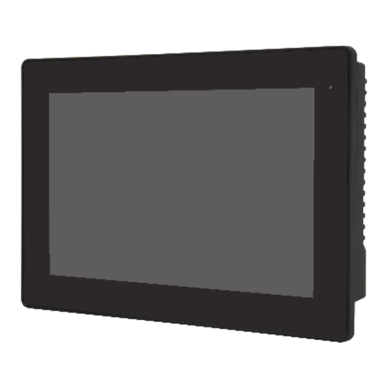
1.4 Brief Description of AUHMI-1XXA Series AUHMI-1XXA series with TB-6030 AD board is an aluminum die casting display, which comes with 10.1”, 15.6” and21.5” color TFT LCD. AUHMI-1XXA series are DC 24V power input, futhermore, the models support resistive touch and projected capacitive touch, and can be high brightness LCD and optical bonding designed for option. -
Page 13: Figure 1.6: Front View Of Auhmi-116Ap/R(H)
Figure 1.6: Front View of AUHMI-116AP/R(H) Figure 1.7: Rear View of AUHMI-116AP/R(H) AUHMI-1XXA Series User Manual... -
Page 14: Figure 1.8: Front View Of Auhmi-121Ap/R(H)
Figure 1.8: Front View of AUHMI-121AP/R(H) Figure 1.9: Rear View of AUHMI-121AP/R(H) AUHMI-1XXA Series User Manual... -
Page 15: Vesa Mounting
1.5 VESA Mounting 1.5.1. 10.1” The AUHMI-110A is designed to be VESA mounted (100 x 100mm) as shown in Picture below. Just carefully place the unit through the hole and tighten the given 4 x M4x8 screws from the rear to secure the mounting. Figure 1.10: AUHMI-110AP/R(H) VESA Mount 1.5.2. -
Page 16: Panel Mount
1.6 Panel Mounting 1.6.1. 10.1” Step1: Embed the main AUHMI-110A machine into the panel frame. Step2: Insert the latch into the specific hole on AUHMI-910C. Step3: Fix the latch with screw. Figure 1.12: AUHMI-110AP/R(H) Panel Mount AUHMI-1XXA Series User Manual... -
Page 17: Figure 1.13: Auhmi-116Ap/R(H)_Auhmi-121Ap/R(H)Panel Mount
1.6.2. 15.6” and 21.5” Step1: Embed the main AUHMI-116A/121A machine into the panel frame. Step2: Insert the latch into the specific hole on AUHMI-116A/121A.(The mounting kits are different from AUHMI-110A) Step3: Fix the latch with screw. Figure 1.13: AUHMI-1106AP/R(H)_AUHMI-121AP/R(H) Panel Mount AUHMI-1XXA Series User Manual... -
Page 18: Cable Cover
1.7 Cable Cover Due to natural mechanical limits, cable cover only fits 15.6” and 21.5” model. Turn the two small brackets into two sides to separate from 15.6” and 21.5” printing. Pre-installation: When installing 15.6” model, make sure steel bracket with 916 printing is fixed on front frame. -
Page 19: Figure 1.14: Auhmi-116Ap/R(H)_Auhmi-121Ap/R(H)Cable Cover
Step1: Insert the cover via the two brackets onto machine. Step2: Fix the cover with 2x M3x6 screws. Figure 1.14: AUHMI-116AP/R(H)_AUHMI-121AP/R(H) AUHMI-1XXA Series User Manual... -
Page 20: Chapter 2 Hardware
Chapter 2 Hardware 2.1 AD Board Specifications AUHMI-1XXA Series User Manual... -
Page 21: Ad Board Diemensions
2.2 AD Board Diemensions Figure 2.1: Dimensions of TB-6030 AUHMI-1XXA Series User Manual... -
Page 22: Jumpers And Connectors Location
2.3 Jumpers and Connectors Location Top Side Bottom Side External IO AUHMI-1XXA Series User Manual... -
Page 23: Jumpers And Connectors
2.4 Jumpers and Connectors 1. DP1 (Display Port Input): (DisplayPort Connector), DisplayPort Interface connector, provide high-quality video and audio input. Signal Name Pin# Pin# Signal Name LANE3- LANE3+ LANE2- LANE2+ LANE1- LANE1+ LANE0- LANE0+ AUX_CHP DP CAB DET AUX_CHN DP HPD RETURN DP 3.3V 2. - Page 24 3. VGA1 (VGA Input): (CRT DB15 Connector), Video Graphic Array Port, provide high-quality video input. Pin# Signal Name CRT_RED CRT_GREEN CRT_BLUE VGA_5V DET_VGA DDCA-SDA HSYNC VSYNC DDCA-SCL 4. J1 (VGA input): (2.0mm Pitch 1 x 12 Pin Wafer), Video Graphic Array Port, provide 12Pin cable to VGA output.
- Page 25 DDCA-SDA DDCA-SCL 5. CN1 (IR Connect): Reserved (2.0mm 1x4 Pin wafer connector), Reserved for IR receiver. Pin# Signal Name 3.3V 6. CN2: (2.0mm 1x3 Pin wafer connector), for external light sensor. Pin# Signal Name Sensor 7. JP1 (OSD): (2.0mm 1x9 Pin wafer connector), On Screen Display menu Control connector. Pin# Signal Name Power Key...
- Page 26 Signal Name Pin# Pin# Signal Name LVDS_12V LCDS_12V BKLT_CTRL BKLT_EN LVDS_VCC5 LVDS_VCC5 LVDS_VCC3 LVDS_VCC3 TXA0N TXA0P TXA1N TXA1P TXA2N TXA2P TXA3N TXA3P TXACN TXACP TXB0N TXB0P TXB1N TXB1P TXB2N TXB2P TXBCN TXB3P TXB3N TXBCP LVDS_DDC_DET CPT-USB_N CPT-USB_P DDCSDA_AUTO LVDS_USB_5V DDCSCL_AUTO LVDS_VCC3 10.
- Page 27 12. SPKR1 (Audio output): (2.0mm 1x2 Pin wafer connector), Amplifier right channel output. Pin# Signal Name R+ (output) R- (output) 13. CN5 (Line In): Line-in (Diameter 3.5mm Jack)Use for the connection of external audio source via a Line-in cable. 14. CN6(USB2.0): (USB Type-A), for external USB2.0 signal input.
- Page 28 17. PW1: (3.50mm Pitch 3-Pin Terminal Block), DC24V power input connector. PW1 (Dinkle ECH350RM-03P) Pin# Power Input DC+24V Ground 18. PW3/PW4: Co-lay, Default PW3 (3.50mm Pitch 2-Pin Terminal Block), DC24V power input connector. PW3/PW4 (PW3: Dinkle ESK381R-2P PW4: CJT A3963WR-2P) Pin# Power Input DC+24V...
-
Page 29: Chapter 3 Osd
Chapter 3 3.1 AD Board OSD Functions Auto Adjust Up/Left Down/Right Power Menu/Entry Power Indicator Power switch: To turn ON or OFF the power Shift the icon to the right side or shift it up Shift the icon to the left side or shift it down Menu: To enter OSD menu for related icon and item. -
Page 30: Osd Controls
When the Burn-in Mode is Unable to Eradicate… If the “RGB” is still on the top left corner of the screen, press to enter “Miscellaneous” and choose “Reset”, and then Yes, and press . When the screen goes black, disconnect power and repeat the above steps. If the “RGB”... -
Page 31: Main Menu
3.3 Main Menu In the PICTURE, there are the following items: ⚫ AutoBacklight ⚫ Backlight ⚫ Brightness ⚫ Contrast ⚫ Sharpness ⚫ Exit AUHMI-1XXA Series User Manual... - Page 32 In the DISPLAY, there are the following items: ⚫ AutoAdjust ⚫ H Position ⚫ V Position ⚫ Disp Rotate ⚫ Exit Disp Rotate In the COLOR, there are the following items: ⚫ Panel Uniformity ⚫ Gamma ⚫ Color Temp ⚫ Color Effect ⚫...
- Page 33 In the INPUT, there are the following items: ⚫ Auto Select ⚫ DP ⚫ HDMI ⚫ Exit In the AUDIO, there are the following items: ⚫ Volume ⚫ Mute ⚫ Exit In the OTHER, there are the following items: ⚫ Reset ⚫...
Need help?
Do you have a question about the AUHMI-1 A Series and is the answer not in the manual?
Questions and answers