Table of Contents
Advertisement
Quick Links
APC-3x93P User Manual
Release Date
_
Revision
Jan. 2014
V1.1
® 2013 Aplex Technology, Inc.
All Rights Reserved.
Published in Taiwan
Aplex Technology, Inc.
15F-1, No.186, Jian Yi Road, Zhonghe District, New Taipei City 235, Taiwan
Tel: 886-2-82262881 Fax: 886-2-82262883 E-mail:
aplex@aplex.com.tw
URL:
www.aplex.com.tw
APC-3x93P User Manual
1
Advertisement
Table of Contents

Related Manuals for Aplex APC-3x93P


Summary of Contents for Aplex APC-3x93P
- Page 1 APC-3x93P User Manual Release Date Revision Jan. 2014 V1.1 ® 2013 Aplex Technology, Inc. All Rights Reserved. Published in Taiwan Aplex Technology, Inc. 15F-1, No.186, Jian Yi Road, Zhonghe District, New Taipei City 235, Taiwan Tel: 886-2-82262881 Fax: 886-2-82262883 E-mail: aplex@aplex.com.tw...
-
Page 2: Warning
Electric Shock Hazard – Do not operate the machine with its back cover removed. There are dangerous high voltages inside. APC-3x93P User Manual... -
Page 3: Packing List
Always disconnect power when the system is not in use. ◆ Disconnect power when you change any hardware devices. For instance, when you connect a jumper or install any cards, a surge of power may damage the electronic components or the whole system. APC-3x93P User Manual... -
Page 4: Table Of Contents
4.2 Intel Graphics Media Accelerator Driver...……………………………..52 4.3 Intel (R) Network Adapter……..………………………………………….55 4.4 Realtek ALC662 HD Audio Driver Installation…….………….…………57 Chapter 5 Touch Screen Installation 5.1 Windows 2000/XP USB Driver Installation for PenMount 6000Series.59 5.2 Installing Software ………………………..........59 5.3 Software Functions……………………...........66 APC-3x93P User Manual... - Page 5 Figures Figure 1.1:Dimensions of APC-3593P…………………………………..…..7 Figure 1.2:Dimensions of APC-3793P…………………………………..…..8 Figure 1.3:Front view of APC-3X93P…………………………………………...9 Figure 1.4:Rear view of APC-3X93P……..…………………………………….9 Figure 2.1: Mainboard Dimensions…………………………………..……..12 Figure 2.2: Jumpers and Connectors Location_ Board Top………………...13 Figure 2.3: Jumpers and Connectors Location_ Board Bottom…………..14 APC-3x93P User Manual...
-
Page 6: Specifications
On board expansion bus Display Display Type 15” TFT-LCD 17” TFT-LCD Max. Resolution 1024x768 1280x1024 Max. Color 262K 16.7M Luminance (cd/m²) View angle(H°/V°) 160/145 170/170 Touch Screen Type Projective Capacitive Interface Light Transmission(%) Touch Screen (option) Type Resistive APC-3x93P User Manual... - Page 7 -20~60 (with Industrial SSD or CF) Storage -30~70℃ temperature(°C) Storage humidity 10 to 90% @ 40°C, non- condensing Certification CE / FCC Class A Operating System Microsoft Windows 7 pro for embedded, Windows embedded standard 7 Support APC-3x93P User Manual...
-
Page 8: Dimensions
1.2 Dimensions Figure 1.1: Dimensions of APC-3593P Figure 1.2: Dimensions of APC-3793P APC-3x93P User Manual... -
Page 9: Brief Description
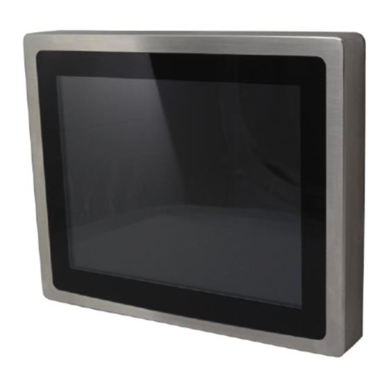
1.3 Brief Description of APC-3x93P APC-3X93P series comes with IP65 certificated and is powered by Intel Atom D2550 to provide low power consumption. The stainless steel chassis design makes it exceptionally suitable for strict hygiene regulations for food/chemical industry, medical, restaurant/kitchen applications, storage management and outdoor /information segment and so on. -
Page 10: Chapter 2 Hardware
9 w/5V/12V/Ring select Serial 1 x RS232 port, DB9 connector for external (COM2) pin 9 w/5V/12V/Ring select 1 x RS422/485 header via CN2 (COM3) 2 x UART via CN3 (COM5,COM6) Digital I/O 8-bit digital I/O Pin header via CN2 APC-3x93P User Manual... - Page 11 Software programmable 1 – 255 second by Super I/O Timer Operating: -20℃ to 70℃ Temperature Storage: -40℃ to 85℃ Humidity 5% - 95%, non-condensing, operating Power 12V /0.95A (Intel Atom N2600 processor with 2GB DDR3 Consumption DRAM) EMI/EMS Meet CE/FCC class A APC-3x93P User Manual...
-
Page 12: Figure 2.1: Mainboard Dimensions
(units :mm) Figure 2.1: Mainboard Dimensions APC-3x93P User Manual... -
Page 13: Installations
HDMI port, one LVDS interface. To satisfy the special needs of high-end customers, CN1 and CN2 and CN3 richer extension functions. The product is widely used in various sectors of industrial control. 2.2.1 Jumpers Setting and Connectors Board Top Figure 2.2: Jumpers and Connectors Location_ Board Top APC-3x93P User Manual... -
Page 14: Figure 2.3: Jumpers And Connectors Location_ Board Bottom
Board Bottom Figure 2.3: Jumpers and Connectors Location_ Board Bottom APC-3x93P User Manual... -
Page 15: Jumpers Setting And Connectors
(5.08mm Pitch 1x3 Pin Connector),DC9V~36V System power input connector。 Pin# Power Input Pin1 DC+9V~32V Pin2 Ground Pin3 4. VGA1: (CRT 2.0mm Pitch 2X6 Pin Header), Video Graphic Array Port, Provide 2x6Pin cable to VGA Port. Signal Name Pin# Pin# Signal Name APC-3x93P User Manual... - Page 16 (Default) Pin1, Pin2, Pin3, Pin4, Pin5 RS422 OFF: (option) Pin1, Pin2, Pin3, Pin4, Pin5 RS485 OFF: (option) Pin1, Pin2, Pin3, Pin4, Pin5 7. RS-422: (Switch),COM1 setting, it provides selectable RS232 or RS422 or RS485 serial signal output. APC-3x93P User Manual...
- Page 17 DTR (Data Terminal Ready) Ground DSR (Data Set Ready) RTS (Request To Send) CTS (Clear To Send) JP1 select Setting (RI/5V/12V) BIOS Setup: Advanced/W83627UHG Super IO Configuration/Serial Port 1 Configuration【RS-232】 RS422 (option): Pin# Signal Name 422_RX+ 422_RX- 422_TX- APC-3x93P User Manual...
- Page 18 (2.0mm Pitch 2x3 Pin Header), COM2 jumper setting, pin 1~6 are used to select signal out of pin 9 of COM2 port. JP2 Pin# Function Close 1-2 COM1 RI (Ring Indicator) (default) Close 3-4 COM1 Pin9=+5V (option) Close 5-6 COM1 Pin9=+12V (option) 10. COM2: APC-3x93P User Manual...
- Page 19 (SD card socket),Secure Digital Memory Card socket. 14. LINE_OUT: (Diameter 3.5mm Jack), HD Audio port, An onboard Realtek ALC662 codec is used to provide high quality audio I/O ports. Line Out can be connected to a headphone or amplifier. APC-3x93P User Manual...
- Page 20 Ethernet port indicate the activity and transmission state of LAN. 17. BUZ1: Onboard buzzer. 18. LED1: LED STATUS. Green LED for Motherboard Power status. 19. LED2: LED STATUS. Green LED for Motherboard Standby Power Good status. 20. CN3 APC-3x93P User Manual...
- Page 21 DTRCOM5_CTS- GPIO24 ICH_GPIO24 ICH_GPIO13 GPIO13 GPIO26 ICH_GPIO26 ICH_GPIO27 GPIO27 Ground Ground PE1_TX_N0 PE1_TX_P0 PE1_RX_N0 PE1_RX_P0 PCIE PCIE Ground Ground CLK_100M_PE1_P CLK_100M_PE1_N PLTRST_BUF- PM_PCIE_WAKE SMBUS SMB_CLK_S SMB_DATA_S SMBUS PE1_CLKRE Ground PCIE PCIE 3P3V_S5 3P3V_S5 3P3V_S5 3P3V_S5 12V_S0 12V_S0 APC-3x93P User Manual...
-
Page 22: Chapter 3 Bios Setup
Press [Delete] key to enter BIOS Setup utility during POST, and then a main menu containing system summary information will appear. Aptio Setup Utility – Copyright (C) 2012 American Megatrends, Inc. Main Advanced Chipset Boot Security Save & Exit APC-3x93P User Manual... -
Page 23: Main Settings
[00:00:08] F1 : General Help F2: Previous Values Access Level Administrator F3:Optimized Defaults F4:Save and Exit ESC Exit Version 2.15.1226. Copyright (C) 2012 American Megatrends , Inc. System Time: Set the system time, the time format is: APC-3x93P User Manual... -
Page 24: Advanced Settings
F4:Save and Exit ESC Exit Version 2.15.1226. Copyright (C) 2012 American Megatrends , Inc. 3.4.1 PCI Subsystem Settings PCI Bus Driver Versio V2.05.02 PCI Common Settings: PCI Latency Timer: [32 PCI Bus Clocks] [64 PCI Bus Clocks] APC-3x93P User Manual... - Page 25 ACPI Sleep State: [Both S1 and S3 available for OS to choose from ] [Suspend Disabled] [S1 only(CPU Stop Clock) ] [S3 only (Suspend to RAM) ] Lock Legacy Resources: [Disabled] [Enabled] S3 Video Repost: [Disabled] [Enabled] APC-3x93P User Manual...
- Page 26 3.4.4 Thermal Configuration CPU Thermal Configuration DTS SMM [Disabled] [Enabled] Platform Thermal Configuration Critical Trip Point [POR] Active Trip Point Lo [55 C] Active Trip Point Hi [71C] Passive Trip Point [95] Passive TC1 Value Passive TC2 Value APC-3x93P User Manual...
- Page 27 USB hardware delays a USB transfer time-out: [20 sec] [10 sec] [5 sec] [1 sec] Device reset time-out: [20 sec] [10 sec] [30 sec] [40 sec] Device power-up delay [Auto] [Manual] Mass Storage Devices: Multiplecard Reader 1 APC-3x93P User Manual...
- Page 28 System temperature1 : +38 System Speed VCORE : +0.968 V +12V : +12.302 V +3.3V : +3.320 V +1.5V : +1.528 V AVCC : +5.203 V VCC5V : +5.216 V VSB5 : +5.203 V VBAT : +3.334 V APC-3x93P User Manual...
- Page 29 EIST: [Enabled] [Disabled] CPU C state Report [Enabled] [Disabled] Enhanced C state [Enabled] [Disabled] CPU Hard C4E [Enabled] [Disabled] CPU C6 state [Enabled] [Disabled] C4 Exit Timing [Fast] [Default] [Slow] C-state POPDOWN [Enabled] [Disabled] C-state POPUP [Enabled] APC-3x93P User Manual...
-
Page 30: Chipset Settings
►Memory Frequency and Timing ►Intel IGD Configuration ******* Memory Information ******* Memory Frequency 800 MHz(DDR3) Tot al Memory 2048 MB DIMM#0 Not Present DIMM#1 2048 MB Memory Frequency and Timing MRC Fast Boot [Enabled] [Disabled] Max TOLUD [Dynamic] APC-3x93P User Manual... - Page 31 [VGA + LVDS] LCD Panel Type [VBIOS Default] [640x480,18bit] [800x480,18bit] [800x600,18bit] [1024x600,18bit ] [1024x768,18bit ] [1280x768,18bit ] [1280x800,18bit ] [1280x1024,18bit] [1366x768,18bit] [1024x768,24bit] [1280x768,24bit] [1280x800,24bit] [1280x1024,24bit] Panel Scaling [Auto] [Force Scaling] [off] [Maintain Aspect Ratio] Active LFP [LVDS] APC-3x93P User Manual...
- Page 32 [Negative] Back light Control Lev [Auto] [Disabled] [Level 8] [Level 1] [Level 2] [Level 3] [Level 4] [Level 5] [Level 6] [Level 7] [Level 8] [Level 9] [Level 10] [Level 11] [Level 12] [Level 13] [Level 14] APC-3x93P User Manual...
- Page 33 [Disabled] PCI-Exp. High Priorit [Disabled] [Enabled] High Precision Event Timer Configuration High Precision Timer [Enabled] [Disabled] SLP_S4 Assertion Widt [1-2 Seconds] [2-3 Seconds] [3-4 Seconds] [4-5 Seconds] Restore AC Power Loss [Last State] [Power off] [Power on] APC-3x93P User Manual...
-
Page 34: Boot Settings
F2: Previous Values Boot Option #2 […] F3:Optimized Defaults Hard Drive BBS Priorities F4:Save and Exit ►CSM Parameters ESC Exit Version 2.15.1226. Copyright (C) 2012 American Megatrends , Inc. Setup Prompt Timeout Bootup Numlock State [On] [off] APC-3x93P User Manual... - Page 35 [Force BIOS] [Keep Current] Interrupt 19 Capture [Immediate] [Postponed] Boot Option #1 Boot Option #2 …… Sets the system boot order [SATA PM:*** … ] Hard Drive BBS Priorities Boot Option #1 SATA PM:***… ****** Disabled CSM Parameters APC-3x93P User Manual...
-
Page 36: Security Settings
Launch Video OpROM po [Do not Launch] [UEFI only] [Legacy only] Other PCI device ROM [UEFI OpROM] [Legacy OpROM] 3.7 Security Settings Aptio Setup Utility – Copyright (C) 2012 American Megatrends, Inc. Main Advanced Chipset Boot Security Save & Exit APC-3x93P User Manual... - Page 37 BIOS setup. This will prevent unauthorized persons from changing your system configurations. Also, the feature is capable of requesting users to enter the password prior to system boot to control unauthorized access to your computer. Users may enable the feature in Security Option APC-3x93P User Manual...
-
Page 38: Save And Exist Settings
BIOS Setup. If the connected panel is not included in the parameter list, display problem will occur. In this case, Please do not change BIOS setup. 3.8.1 North Bridge Configuration BIOS SETUP UTILITY Chipset North Bridge Chipset Configuration ENABLE: Allow APC-3x93P User Manual... - Page 39 Memory Remap Feature: [Enabled] [Disabled] Memory Hole: [Disabled] [15MB-16MB] Initate Graphic Adapter: Select which graphics controller to use as the primary boot device. [IGD] [PCI/IGD] IGD Graphics Mode Select: [Enabled, 64MB] [Disabled] [Enabled, 32MB] [Enabled, 128MB] Video Function Configuration: APC-3x93P User Manual...
- Page 40 V02.61 © Copyright 1985-2006 American Mega trends , Inc. DVMT Mode Select: [DVMT Mode] [FIXED Mode] DVMT/FIXED Memory Size: [256MB] [128MB] [Maximum DVMT] Boot Display Device: [BIOS-Default] [CRT] [LVDS] [CRT + LVDS] Flat Panel Type: [1024x 768 18bit 1ch] APC-3x93P User Manual...
- Page 41 [Level7] Note: Panel support PWM Function. Backlight Control Mode: [DC] [PWM] Backlight Image Adaptation: [VBIOS-Default] [BIA Disabled] [BIA Enabled at Level1] [BIA Enabled at Level2] [BIA Enabled at Level3] [BIA Enabled at Level4] [BIA Enabled at Level5] APC-3x93P User Manual...
- Page 42 Discard Changes and Ext Exit Without Saving Quit without saving? [Yes] [No] Save Changes and Reset Save & reset Save Configuration and reset? [Yes] [No] Discard Changes and Reset Reset Without Saving Reset without saving? [Yes] [No] APC-3x93P User Manual...
-
Page 43: Exit Options
Exit Exit Options Exit system setup Save Changes and Exit after saving the Discard Changes and Exit changes Discard Changes F10 key can be used For this operation Load Optimal Defaults Load Failsafe Defaults ← Select Screen APC-3x93P User Manual... - Page 44 F7 key can be used for this operation) [OK] [Cancel] Load Optimized Defaults: Load Optimized Defaults? F9 key can be used for this operation) [OK] [Cancel] Load Fail-Safe Defaults: Load Fail-Safe Defaults? F9 key can be used for this operation) [OK] [Cancel] APC-3x93P User Manual...
-
Page 45: Chapter 4 Installation Of Drivers
VGA driver, LAN drivers, Audio driver Installation instructions are given below. Important Note: After installing your Windows operating system (Windows 7), you must install first the Intel Chipset Software Installation Utility before proceeding with the installation of drivers. APC-3x93P User Manual... -
Page 46: Intel Chipset Driver
4.1 Intel Chipset Driver To install the Intel chipset driver, please follow the steps below. Step 1. Select Intel (R) Chipset NM10 Express from the list Step 2. Click Next to setup program. APC-3x93P User Manual... - Page 47 Step 3. Read the license agreement. Click Yes to accept all of the terms of the license agreement. Step 4. Click Next to continue. APC-3x93P User Manual...
- Page 48 Step 5. Click Next. Step 6. Select Yes, I want to restart this computer now. Click Finish, then remove any installation media from the drives. APC-3x93P User Manual...
-
Page 49: Intel Graphics Media Accelerator Driver
4.2 Intel Graphics Media Accelerator driver To install the VGA drivers, follow the steps below to proceed with the installation. Step 1.Select Intel(R) VGA Chipset Driver. Step 2. Tick Automatically run WinSAT and enable the Windows Aero desktop theme(if supported). APC-3x93P User Manual... - Page 50 Step 3. Read license agreement. Click Yes. Step 4. Click Next. APC-3x93P User Manual...
- Page 51 Step 5. Click Next. Step 6. Select Yes, I want to restart this computer now. APC-3x93P User Manual...
-
Page 52: Intel (R) Network Adapter
4.3 Intel (R) Network Adapter To install the Intel (R) Network Adapter device driver, please follow the steps below. Step 1. Select Realtek RTL8111D Driver. Step 2. Click Next to continue. APC-3x93P User Manual... - Page 53 Step 3. Click Install to begin the installation. Step 4. Click Finish to exist the wizard. APC-3x93P User Manual...
-
Page 54: Realtek Alc662 Hd Audio Driver Installation
4.4 Realtek ALC662 HD Audio Codec Driver Installation To install the Realtek ALC662 HD Audio Codec Driver, please follow the steps below. Step 1. Select Realtek AL662 Audio Codec Driver from the list Step 2. Click Next to continue. APC-3x93P User Manual... - Page 55 Step 3. Click Yes, I want to restart my computer now. Click Finish to complete the installation. APC-3x93P User Manual...
-
Page 56: Chapter 5 Touch Screen Installation
Please make sure your USB controller device had plugged in advance. When the system first detects the controller board, a screen appears that shows “Unknown Device”. Do not use this hardware wizard. Press Cancel. APC-3x93P User Manual... - Page 57 Step 1. Insert the product CD, the screen below would appear. Click touch panel driver. Step 2. Click Next to continue. APC-3x93P User Manual...
- Page 58 Step 3. Select I accept the terms of the license agreement. Click Next. Step 4. Tick Install RS232 interface driver. Click Next. APC-3x93P User Manual...
- Page 59 Step 5. Select None. Click Next. Step 6. Click OK. Step 7. Tick Support Muti-Monitor System. Click Next. APC-3x93P User Manual...
- Page 60 Step 8. Go to C:\Program Files\eGalaxTouch. Click Next. Step 9. Click Next. APC-3x93P User Manual...
- Page 61 Step 10. Tick Create a eGalaxTouch Utility shortcut on desktop. Click Next. Step 11. Wait for installation. APC-3x93P User Manual...
-
Page 62: Software Functions
Step 12. Click Yes to do 4 point calibration. 5.3 Software Functions General In this window, you can see there is USB Controller. Click OK to continue. Monitor Mapping to adjust touch panel to search for device APC-3x93P User Manual... - Page 63 Beep Beep On Touch Beep On Release Beep From System Beep Beep From Sound Card Linearization Style 9 points 25 points Double Click Time Shorter Longer Double Click Area Smaller Bigger Normal mode Simulate the mouse mode APC-3x93P User Manual...
- Page 64 Option Function Enable Constant Touch Enable Auto Right Click Enable Touch Enable Cursor Stabilization Constant Touch Area Auto Right Click Time APC-3x93P User Manual...
- Page 65 Do 4 points alignment to match display. Clear and Calibrate Clear linearization parameter and do 4 points alignment. Linearization Do 9 points linearization for better touchscreen linearity. Draw Test Do draw test to verify the touch accuracy. APC-3x93P User Manual...
- Page 66 Display In this window, it shows the mode of display. Enable Multiple Monitors. Map to main display if system has only one display monitor Full Screen Lower Screen Left Screen Upper Screen Right Screen APC-3x93P User Manual...
- Page 67 Other Other mode of display. Quarter1~4 and Customized area. Active Area Drag active area to enable Active Area Function. APC-3x93P User Manual...
- Page 68 Hardware Saturn Hardware Configuration APC-3x93P User Manual...
- Page 69 About To display information about eGalaxTouch and its version. APC-3x93P User Manual...
- Page 70 If you have an older version of the PenMount Windows 2000/XP driver installed in your system, please remove it first. Follow the steps below to install the PenMount DMC6000 Windows 2000/XP driver. Step 1. Insert the product CD, the screen below would appear. Click touch panel driver. Step 2. Click Next to continue. APC-3x93P User Manual...
- Page 71 Step 3. Read the license agreement. Click I Agree to agree the license agreement. Step 4. Choose the folder in which to install PenMount Windows Universal Driver. Click Install to start the installation. APC-3x93P User Manual...
- Page 72 Step 5. Wait for installation. Then click Next to continue. Step 6. Click Continue Anyway. APC-3x93P User Manual...
- Page 73 The functions of the PenMount Control Panel are Device, Multiple Monitors ,Tools and About, which are explained in the following sections. Device In this window, you can find out that how many devices be detected on your system. APC-3x93P User Manual...
- Page 74 Advanced Calibration Advanced Calibration uses 4, 9, 16 or 25 points to effectively calibrate touch panel linearity of aged touch screens. Click this button and touch the red squares in sequence with a stylus. To skip, press ESC’. APC-3x93P User Manual...
- Page 75 -calibration 0 ( Standard Calibration) Dmcctrl.exe - calibration ($) 0= Standard Calibration 4=Advanced Calibration 4 9=Advanced Calibration 9 16=Advanced Calibration 16 25=Advanced Calibration 25 Step 1. Please select a device then click “Configure”. You can also double click the device too. APC-3x93P User Manual...
- Page 76 Step 2.Click “Standard Calibration” to start calibration procedure NOTE: The older the touch screen, the more Advanced Mode calibration points you need for an accurate calibration. Use a stylus during Advanced Calibration for greater accuracy. Please follow the step as below: APC-3x93P User Manual...
- Page 77 Step 3.Come back to “PenMount Control Panel” and select Tools then click Advanced Calibration. Step 4. Select Device to calibrate, then you can start to do Advanced Calibration. NOTE: Recommend to use a stylus during Advanced Calibration for greater accuracy. APC-3x93P User Manual...
- Page 78 Setting APC-3x93P User Manual...
- Page 79 About This panel displays information about the PenMount controller and driver version. APC-3x93P User Manual...
- Page 80 Please note once you turn on this function the rotating function is disabled. Enable the multiple display function as follows: 1. Check the Enable Multiple Monitor Support box; then click Map Touch Screens to assign touch controllers to displays. APC-3x93P User Manual...
- Page 81 4. Touching all screens completes the mapping and the desktop reappears on the monitors. 5. Select a display and execute the “Calibration” function. A message to start calibration appears. Click OK. APC-3x93P User Manual...
- Page 82 This panel displays information about the PenMount controller and this driver version. PenMount Monitor Menu Icon The PenMount monitor icon (PM) appears in the menu bar of Windows 2000/XP system when you turn on PenMount Monitor in PenMount Utilities. APC-3x93P User Manual...
- Page 83 2. Choose the rotate function (0°, 90°, 180°, 270°) in the 3rd party software. The calibration screen appears automatically. Touch this point and rotation is mapped. NOTE: The Rotate function is disabled if you use Monitor Mapping APC-3x93P User Manual...
Need help?
Do you have a question about the APC-3x93P and is the answer not in the manual?
Questions and answers