Table of Contents
Advertisement
Quick Links
ADP-1224A Display
User Manual
Revision
Date
Version
Remark
Aug. 2012
V1.0
® 2012 Aplex Technology, Inc.
All Rights Reserved.
Published in Taiwan
Aplex Technology, Inc.
15F-1, No.186, Jian Yi Road, Zhonghe District, New Taipei City 235, Taiwan
Tel: 886-2-82262881
Fax: 886-2-82262883
E-mail:
aplex@aplex.com.tw
URL:
www.aplex.com.tw
ADP-1224A User Manual
1
Advertisement
Table of Contents

Related Manuals for Aplex ADP-1224A


Summary of Contents for Aplex ADP-1224A
- Page 1 User Manual Revision Date Version Remark Aug. 2012 V1.0 ® 2012 Aplex Technology, Inc. All Rights Reserved. Published in Taiwan Aplex Technology, Inc. 15F-1, No.186, Jian Yi Road, Zhonghe District, New Taipei City 235, Taiwan Tel: 886-2-82262881 Fax: 886-2-82262883 E-mail: aplex@aplex.com.tw...
-
Page 2: Warning
Disclaimer This information in this document is subject to change without notice. In no event shall Aplex Technology Inc. be liable for damages of any kind, whether incidental or consequential, arising from either the use or misuse of information in this document or in any related materials. -
Page 3: Table Of Contents
3.3 Electrical Specifications…………………………………………………...15 3.4 Installation of Control Board……………………………………………...16 Chapter 4 Installation 4.1 Windows 2000/XP Driver Installation…………………………………….17 4.2 Configuring PenMount Windows 2000/XP Driver………………………21 4.3 Uninstall PenMount Windows 2000/XP Driver………………………….31 Chapter 5 Software 5.1 Software Functions………………………………………………………..32 5.2 Software Function Descriptions……………………………………….…33 ADP-1224A User Manual... - Page 4 Appendix B: Controller IC Specifications ………………………………41 Figures Figure 1.1: Dimensions of ADP-1224A….……………………………………..6 Figure 1.2: Front View of ADP-1224A………………………………………….7 Figure 1.3: Rear View of ADP-1224A………………………………………….7 Figure 3.1: Bird Eye’s View of Control Board………………………………14 Figure 3.2: Mechanical Drawing of Control Board…………………………14 ADP-1224A User Manual...
-
Page 5: Specifications
Construction Steel Housing IP Rating Front Panel IP65 Mounting VESA 100x100 Mount Dimensions (WxHxD) 557(W)x362(H)x68(D) mm Environmental Operating Temperature 0~50 °C Storage Temperature -20~60 °C 10~90% @40 ゚ C non-condensing Storage Humidity Certificate Meet CE/FCC Class A ADP-1224A User Manual... -
Page 6: Dimensions
1.2 Dimensions Figure 1.1: Dimensions of the ADP-1224A ADP-1224A User Manual... -
Page 7: Brief Description
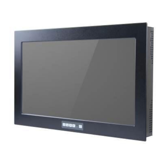
1.3 Brief Description of the ADP-1224A The ADP-1224A is a 21.5" TFT LCD Display that comes with viewing angle of 170 (H) degrees and 160 (V) degrees, and more outstanding features, thus giving you the best in monitoring and control applications. -
Page 8: Display Mode
1.4 Display Mode Display Mode Hori. Sync (KHz) Vert. Sync. (Hz) VGA 640 x 480 SVGA 800 x 600 XGA 1024 x 768 1152 x 864 SXGA 1280 x 1024 Full HD 1920 x 1080 ADP-1224A User Manual... -
Page 9: Front Panel Controls
Please don’t let your fingers go until the AC power cord is connected again and the wording of “RGB” appears on the top left corner of your screen, and wait for 3 seconds. Under the non-signal entry situation, if is seen, exit is thus successfully made. Cable Not Connected ADP-1224A User Manual... -
Page 10: Osd Controls
2.) If the “RGB” is not found, disconnect the AC power cord first. Then press the buttons (don’t let them go) until the AC power cord is connected, and wait for 2 to 3 seconds. When “RGB” appears, repeat the above steps. 3.) Functions of OSD Keys ADP-1224A User Manual... -
Page 11: Main Menu
Exit For Color, check out the following: Contrast Brightness Color Adjust Color Temp Back For Image setting, check out the following: Clock Phase Gamma Sharpness Back ADP-1224A User Manual... - Page 12 Simplified Chinese Japanese In the Misc menu, there are: Signal Source Select VGA: Analogue VGA Input Select DVI: Digital DVI-D Input Select AV: Composite Video Input Select SV: S-Video Video Input Reset Back ADP-1224A User Manual...
-
Page 13: Ad Board (Va-3600) Osd Functions
(don’t let them go) until the AC power cord is connected, and wait for 2 to 3 seconds. When “RGB” appears, repeat the above steps. 6.) Functions of OSD Keys Auto Adjust Up/Left Down/Right Power Menu/Entry Power Indicator ADP-1224A User Manual... -
Page 14: Introduction To Penmount Control Board
The size of the board is 26 by 60mm, and it has two connectors and one dipswitch on-board. Figure 3.1: Bird’s Eye View of PenMount 9036 Figure 3.2: Mechanical Drawing of PenMount 9036 ADP-1224A User Manual... -
Page 15: Features
Baud Rate: 19200 and 9600 baud rate selection Resolution: 1024x1024 (10-bit A/D converter inside) Power Input: 5V ~ 12V DC Power Consumption: 12V: 24mA+ i where (i=v/touch screen sheet R) 5V: 20mA+ i where (i=v/touch screen sheet R) ADP-1224A User Manual... -
Page 16: Installation Of Control Board
PnP enable or disable Disable Enable Touch screen type 5-wire 4-, 8-wire Touch screen type 4-, 8-wire 5-wire 6. Turn on power to the computer and the display. 7. Install the software drivers and utilities and calibrate the touch screen. ADP-1224A User Manual... -
Page 17: Windows 2000/Xp Driver Installation
Follow the steps below to install the PenMount Windows 2000/XP driver. 1. When the system first detects the controller board, a screen appears that shows “Unknown Device”. Do not use this hardware wizard. Press Cancel. ADP-1224A User Manual... - Page 18 2. Insert the PenMount Driver CD-ROM. Go to the Windows 2000-XP Driver folder. Click setup.exe. 3. The screen displays the installation wizard for the PenMount software. Click “Next”. ADP-1224A User Manual...
- Page 19 4. A License Agreement appears. Click “I accept…” and “Next”. 5. The “Ready to Install the Program” screen appears. Select “Install”. ADP-1224A User Manual...
- Page 20 6. The next screen is “Hardware Installation”. Select “Continue Anyway”. 7. The “InstallShield Wizard Completed” appears. Click “Finish”. ADP-1224A User Manual...
-
Page 21: Configuring Penmount Windows 2000/Xp Driver
Advanced Calibration Advanced Calibration uses 4, 9, 16 or 25 points to effectively calibrate touch panel linearity of aged touch screens. Click this button and touch the red squares in sequence with a stylus. To skip, press ‘ESC’. ADP-1224A User Manual... - Page 22 NOTE: The older the touch screen is, the more Advanced Mode calibration points you need for an accurate calibration. Use a stylus during Advanced Calibration for greater accuracy. ADP-1224A User Manual...
- Page 23 Plot Calibration Data Check this function and a touch panel linearity comparison graph appears when you have finished Advanced Calibration. The blue lines show linearity before calibration and black lines show linearity after calibration. ADP-1224A User Manual...
- Page 24 Touch the screen with your finger or a stylus and the drawing screen will register touch activity such as left, right, up, down, pen up, and pen down. ADP-1224A User Manual...
- Page 25 The Multiple Monitor function is for use with multiple displays only. Do not use this function if you have only one touch screen display. Please note once you turn on this function the rotating function is disabled. ADP-1224A User Manual...
- Page 26 Enable the multiple display function as follows: 1. Check the Enable Multiple Monitor Support box; then click Map Touch Screens to assign touch controllers to displays. 2. When the mapping screen message appears, click OK. ADP-1224A User Manual...
- Page 27 2. The Rotating function is disabled if you use the Multiple Monitor function. 3. If you change the resolution of display or screen address, you have to redo Map Touch Screens, so the system understands where the displays are. ADP-1224A User Manual...
- Page 28 This panel displays information about the PenMount controller and this driver version. PenMount Monitor Menu Icon The PenMount monitor icon (PM) appears in the menu bar of Windows 2000/XP system when you turn on the PenMount Monitor in the PenMount Utilities. The PenMount Monitor has the following functions: ADP-1224A User Manual...
- Page 29 Right and Left Button functions. Pen Stabilizer Check this function to reduce cursor vibration for relatively unstable touch screens, or where there may be excess vibration. Normally this function is not checked. Exit Exits the PenMount Monitor function. ADP-1224A User Manual...
- Page 30 2. Choose the rotating function (0°, 90°, 180°, 270°) in the 3 party software. The calibration screen appears automatically. Touch this point and rotation is mapped. NOTE: The rotating function is disabled if you use Monitor Mapping ADP-1224A User Manual...
-
Page 31: Uninstall Penmount Windows 2000/Xp Driver
2. Go to Settings, then Control Panel, and then click Add/Remove program. Select PenMount DMC9000 and click the Add/Remove button. 3. Select PenMount DMC9000 and DMC9100. Click the Remove button. 4. Select “Yes” and “Close” to remove the PenMount Windows 2000/XP driver, and reboot the system. ADP-1224A User Manual... -
Page 32: Software Functions
●■ ● ●■ ●■ ● Right button ● ● ● ● Hide cursor ● ● Double click area and speed adjustable ● ● ●■ ● ●■ About ● RS-232 Interface (9000 series) ■ USB Interface (5000 series) ADP-1224A User Manual... -
Page 33: Software Function Descriptions
5. The PenMount 9000 Windows 2000/XP v4.01 or greater software driver Before using Multiple Monitors you must have two or more monitors that are in extension mode. For display cards that support multiple monitors, we suggest you consider Matrox, ADP-1224A User Manual... - Page 34 PenMount 9000 can support up to six control boards, and the drivers for PenMount 5000 support up to 16 Comparing Functions The difference between the Multiple Monitors function and the Multiple Devices function are illustrated below: The Multiple Monitors function shown above extends the screen into 2 or more monitors. ADP-1224A User Manual...
- Page 35 If you use a rotating monitor, you will need a display card such as from nVidia, Intel, SMI or ATI and software such as Portrait Pivot Pro. For software operation and features, please refer to your software manual. Configuring the rotation function is easy. Select this option and a ‘point’ appears for you ADP-1224A User Manual...
- Page 36 Once the point is touched, the software driver understands which degree you plan to rotate your display. The rotation function supports 90, 180 and 270 degrees rotation. 0 degrees ADP-1224A User Manual...
- Page 37 90 degrees 180 degrees 270 degrees ADP-1224A User Manual...
- Page 38 The plot calibration data function shows the linearity status of the touch screen. This is only a support function for the user. The exact linearity of a touch screen requires a linearity test machine. ADP-1224A User Manual...
- Page 39 The Double-Click Area and Speed function lets the user adjust the double-click area and speed to their personal preference. About This option shows the exact version of the drivers and controller firmware. Updated drivers are available for download on the PenMount website. ADP-1224A User Manual...
- Page 40 PIN 2 PIN 1 Ground Ground Ground Connector Pin Definitions for Power and RS-232 Power Lines RS-232 Interface Pin # PIN 1 PIN 2 PIN 3 PIN 4 PIN 5 PIN 6 Definition Ground 5V~12V power Ground ADP-1224A User Manual...
- Page 41 -1.0V to +13.0V to Ground: DC Current per I/O Pin: 40.0 mA DC Current Vcc and GND Pins: 300.0 mA Driver Software DOS, Windows 3.11, Windows 95/2000/XP, Windows NT/2000/XP, Linux, QNX, Windows CE (for both X86 and SA CPUs) ADP-1224A User Manual...
Need help?
Do you have a question about the ADP-1224A and is the answer not in the manual?
Questions and answers