
Related Manuals for Leadshine DM805-AI


Summary of Contents for Leadshine DM805-AI
- Page 1 Hardware Installation Manual for DM805-AI Digital Stepper Drive with Analog 0-5V Input www.leadshine.com HWMN-DMAI-R20110627...
- Page 2 Leadshine reserves the right to make changes without further notice to any products herein to improve reliability, function or design. Leadshine does not assume any liability arising out of the application or use of any product or circuit described herein; neither does it convey any license under its patent rights of others.
- Page 3 Read this manual carefully before trying to install the stepper drive into your system. The person setup the stepper drive should have a better understanding on electronics and mechanics. Contact Leadshine technical guys when have questions on this document. Notice Make sure the power supply voltage dose not exceed the drive’s input range.
-
Page 4: Table Of Contents
Table of Contents 1. Introduction, Features and Applications........................1 Introduction................................1 Features..................................1 Applications................................1 2. Specifications................................. 2 General Specifications..............................2 Electrical Specifications............................. 2 Input Voltage...............................2 Pulse Input Frequency............................2 Velocity Control..............................2 Operating Environment.............................. 2 Mechanical Specifications............................3 Elimination of Heat..............................3 3. Connectors and Interface..............................4 4. - Page 5 Analog 0-5V Speed Mode............................15 Low/High Speed Mode............................16 External Potentiometer Mode...........................17 Pulse/Direction Mode...............................18 9. Wiring Notes.................................18 10. Configure the Drive..............................19 Auto Configuration by SW4............................ 19 Selecting Operating Mode............................20 Microstep Resolution Selection..........................20 Current Settings................................20 Dynamic current setting........................... 20 Idle current setting............................21 11.
-
Page 6: Introduction, Features And Applications
Introduction The DM805-AI is a 0-5V input stepper drive with built-in oscillator which is based on the latest digital control algorithm. It brings a unique level of system smoothness, providing optimum torque and nulls mid-range instability. Motor self-test and parameter auto-setup technology offers optimum responses with different motors and easy-to-use. -
Page 7: Specifications
DM805-AI Hardware Installation Manual 2. Specifications General Specifications Parameter Typical Unit Isolation Resistance MΩ Logic Signal Current Electrical Specifications Input Voltage Input Voltage Typical Unit Drive Model DM805-AI Pulse Input Frequency Pulse Input Frequency Typical Unit Drive Model DM805-AI Velocity Control... -
Page 8: Mechanical Specifications
DM805-AI Hardware Installation Manual 5.9m/s Vibration Storage Temperature -20℃ - 65℃ (-4℉ - 149℉) Mechanical Specifications 118 [ 4.646] 112 [ 4.409] 112 [ 4.409] Elimination of Heat Driver’s reliable working temperature should be <70℃(158℉), and motor working temperature should be <80℃(176℉);... -
Page 9: Connectors And Interface
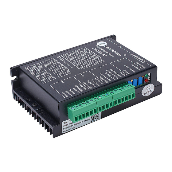
3. Connectors and Interface The DM805-AI has three connectors, connector for digital I/O signals connections, connector for analog 0-5V signal connections and connector for power and motor connections. The three parameters are used to preset or adjust the speed, acceleration and deceleration ramp. -
Page 10: Operating Mode
DM805-AI Hardware Installation Manual 4. Operating Mode The DM805-AI supports four operating modes selected by the DIP switch SW7 and SW8, shown as the following table. Mode Description 0~5V Speed Analog 0-5V Speed Mode Lo/Hi Speed Low and High Speed Mode... -
Page 11: Signal Sequence
Signal Sequence After power-up, the DM805-AI does not response to the analog 0-5V input immediately. The Enable and Run signal should be activated prior to the analog 0-5V input. The drive is enabled when the Enable/Disable input is unconnected and the motor shaft has holding torque at that time. -
Page 12: Low/High Speed Mode
Signal Sequence After power-up, the DM805-AI does not make the motor run immediately. The Enable and Run signal should be activated firstly. Drive is enabled when the Enable/Disable input is unconnected. After Run signal is activated, the Speed can be applied to the drive for low/high speed selection. -
Page 13: Ramp Shaping
DM805-AI Hardware Installation Manual High Speed Speed Low Speed Direction Negative Positive Stop Run/Stop Enable/Disable Enable Ramp Shaping When motor speed switches between low and high or changes direction, the acceleration/deceleration ramp adjusted by the Ramp potentiometer will be inserted automatically for smooth motion. -
Page 14: Signal Sequence
DM805-AI Hardware Installation Manual Motor Speed 25rps Fully CW of HiSpeed Potentiometer Dead Band Analog Input 0rps 2.5V Half CW of HiSpeed Potentiometer -25rps Signal Sequence 2.5-5V Input Positive Direction Negative Direction 0-2.5V Input Stop Run/Stop Enable/Disable Ramp Shaping There are two potentiometers Accel and Decel for adjusting the acceleration ramp and deceleration ramp, respectively. When the input ramp exceeds the value set by the potentiometer, the actual output ramp will be limited by the potentiometer value. -
Page 15: Pulse/Direction Mode
DIP switch SW5 and SW6. 5. Control Signal Requirement Pulse/Direction Mode DM805-AI can support Pulse/Direction and CW/CCW control signal modes. In order to avoid some fault operations and deviations, PUL, DIR and ENA should abide by some rules, shown as following diagram: Remark: ENA must be ahead of DIR by at least 5us. -
Page 16: Connecting The Motor
Low level width not less than 2.5us. 6. Connecting the Motor The DM805-AI can drive any 2-pahse and 4-pahse hybrid stepping motors. 4-lead Motors Connections 4 lead motors are the least flexible but easiest to wire. Speed and torque will depend on winding inductance. In setting the drive output current, multiply the specified phase current by 1.4 to determine the peak output current. -
Page 17: 8-Lead Motors Connections
DM805-AI Hardware Installation Manual 8-lead Motors Connections 8 lead motors offer a high degree of flexibility to the system designer in that they may be connected in series or parallel, thus satisfying a wide range of applications. Series Connections A series motor configuration would typically be used in applications where a higher torque at lower speeds is required. Because this configuration has the most inductance, the performance will start to degrade at higher speeds. -
Page 18: Power Supply Selection
7. Power Supply Selection The DM805-AI can match medium and small size stepping motors (from NEMA frame size 14 to 34) made by Leadshine or other motor manufactures around the world. To achieve good driving performances, it is important to select supply voltage and output current properly. - Page 19 DM805-AI Hardware Installation Manual The recommended power supply voltage for DM805-AI is 24-72VDC: HWMN-DM-R2011060...
-
Page 20: Typical Connection
Analog 0-5V Speed Mode The 5V output of DM805-AI is connected to the COM+. The input signal is activated when it is short circuit to the signal GND. When the Limit switch is activated, the motor shaft will be free and the red indicator is on. -
Page 21: Low/High Speed Mode
DM805-AI Hardware Installation Manual Low/High Speed Mode Ramp Accel/Ramp LoSpeed DecelLoSpeed HiSpeed HiSpeed COM+ Run/Stop/Pulse Run/Stop Direction/+Limit Direction Speed/(-)Limit Speed Enable/Disable DM805-AI Disable Signal GND +5V Output 0~5V Input Signal GND Signal GND Power GND 20-80VDC +20-80VDC Motor A+ Motor A-... -
Page 22: External Potentiometer Mode
DM805-AI Hardware Installation Manual External Potentiometer Mode Accel/Ramp Accel Decel/LoSpeed Decel HiSpeed HiSpeed COM+ Run/Stop/Pulse Run/Stop Direction/+Limit +Limit Speed/(-)Limit -Limit Enable/Disable DM805-AI Disable Signal GND +5V Output 0-2.5V Negative 0~5V Input 2.5-5V Positive Signal GND Signal GND Power GND 20-80VDC... -
Page 23: Pulse/Direction Mode
DM805-AI Hardware Installation Manual Pulse/Direction Mode A complete stepping system should include stepping motor, stepping drive, power supply and controller (pulse generator). COM+ Run/Stop/Pulse Direction/+Limit Speed/-Limit Disable Enable/Disable DM805-AI Signal GND +5V Output 0~5V Input Signal GND Tach Output Power GND... -
Page 24: Configure The Drive
10. Configure the Drive The DM805-AI uses an 8-bit DIP switch to set operating mode, microstep resolution and motor operating current as follows. The dynamic current setting by SW1, SW2 and SW3 is active for all operating mode. The microstep resolution setting by SW5 and SW6 only takes effect in Pulse/Direction mode. -
Page 25: Selecting Operating Mode
DM805-AI Hardware Installation Manual Selecting Operating Mode Mode Description 0~5V Speed Analog 0-5V Speed Mode Lo/Hi Speed Low and High Speed Mode External POT External Potentiometer Speed Mode Pulse/Direction Pulse and Direction Position Mode Note: Remove power supply before changing operating mode. -
Page 26: Idle Current Setting
Idle current setting When there is no pulse applied to the DM805-AI and the time exceeds the idle-time which can be configured via the PC based software, the drive goes into idle status. SW4 is used to set the idle-current, OFF meaning that the motor coil current is automatic reduced, and ON meaning that current is the same as the selected dynamic current. -
Page 27: Protection Functions
11. Protection Functions To improve reliability, the drive incorporates some built-in protection functions. The DM805-AI uses one RED LED to indicate what protection has been activated. The periodic time of RED is 3 or 5 s (seconds), and how many times the RED turns on indicates what protection has been activated. -
Page 28: Frequently Asked Questions
DM805-AI Hardware Installation Manual 12. Frequently Asked Questions In the event that your drive doesn’t operate properly, the first step is to identify whether the problem is electrical or mechanical in nature. The next step is to isolate the system component that is causing the problem. As part of this process you may have to disconnect the individual components that make up your system and verify that they operate independently. -
Page 29: Appendix
Leadshine Technology Co., Ltd. warrants its products against defects in materials and workmanship for a period of 12 months from shipment out of factory. During the warranty period, Leadshine will either, at its option, repair or replace products which proved to be defective. -
Page 30: Contact Us
DM805-AI Hardware Installation Manual CONTACT US China Headquarters Address: Floor 11, Block A3, Nanshan iPark, Xueyuan Avenue 1001, Shenzhen, Guangdong, 518055, China Web: http://www.leadshine.com Sales Hot Line: Tel: 86-755-2641-7674 (for Asia, Australia, Africa areas) 86-755-2640-9254 (for Europe areas) 86-755-2641-7617 (for Europe areas) Fax: 86-755-2640-2718 Email: sales@leadshine.com.
Need help?
Do you have a question about the DM805-AI and is the answer not in the manual?
Questions and answers