Table of Contents
Advertisement
Available languages
Available languages
Quick Links
W A R N I N G ! R e a d a l l i m p o r t a n t i n f o r m a t i o n n o t i c e s o n p a g e s 2 – 4
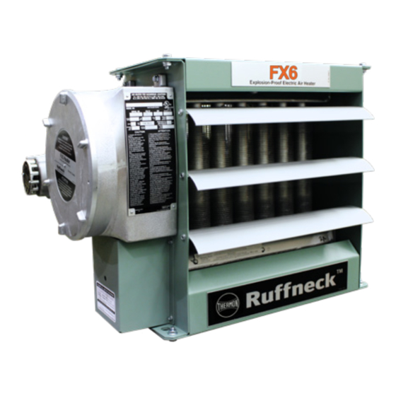
Electric Forced Air Heaters for Hazardous Locations
FX6 Series
Installation Operation Maintenance Instructions
Model Coding
FX6 - 480
Model
Heater Voltage
Series
208V, 240V,
480V, 600V
6th Generation
approved Locations
C
US
Listed
The Electric Forced Air Heaters are c UL us listed certified for the following locations:
Class I, Division 1 & 2, Groups C & D; Class II, Division 1, Groups E, F & G; Class II,
Division 2, Groups F & G; Class I, Zones 1 & 2, Groups IIA & IIB; Zones 20, 21 & 22;
Temperature Code T3B 329˚F (165˚C) (50 Hz & 60 Hz Models)
For details of hazardous locations with potential for explosion, refer to the Canadian
Electrical Code, Part 1, Section 18 or National Electrical Code articles 500–516.
3
60 - 350
Hertz
50, 60
Heater Kilowatts
Phase
÷ 10
1, 3
-
T
T – XT-311 Thermostat with slim
junction box
XT-411 Thermostat with
large junction box
D – Built-in disconnect
C – Heresite
coating
®
A – Stainless steel cabinet
U – Continuous fan
L – Large junction box
P – Built-in pilot light
Part No. 13988 Rev 1.06 Printed in Canada
ISO 9001
Advertisement
Chapters
Table of Contents

Related Manuals for Thermon Ruffneck FX6 Series


Summary of Contents for Thermon Ruffneck FX6 Series
- Page 1 W A R N I N G ! R e a d a l l i m p o r t a n t i n f o r m a t i o n n o t i c e s o n p a g e s 2 – 4 ISO 9001 Electric Forced Air Heaters for Hazardous Locations FX6 Series...
-
Page 2: Table Of Contents
TABLE OF CONTENTS A. Heater Maintenance Checklist Preventative Maintenance Grid .................................3 Periodic ............................................. 4 Annual ............................................4 B. Important Notices C. Troubleshooting Tips D. Installation Mechanical ..........................................7 Electrical ..........................................9 Wiring Schematics ......................................11 E. FX6 Technical Data 50 Hz Electric Heaters .....................................12 60 Hz Electric Heaters ....................................13 F. -
Page 3: Heater Maintenance Checklist
Photocopy HEATER MAINTENANCE CHECKLIST this page for reuse. Heater Model Date of Maintenance Serial Number Maintenance Done By Comments WARNING Disconnect heater from power supply at integral Lock the switch in the “OFF” (open) position and/or tag the WARNING disconnect or fuse box before opening enclosures switch to prevent unexpected power application. -
Page 4: Periodic
For severe duty conditions such as indication that fluid has leaked from the core. arctic duty or drilling rigs, Thermon recommends If any fluid leakage occurs from the heater, the contactor be replaced every two years. -
Page 5: Important Notices
IMPORTANT NOTICES do not circumvent this device to operate the heater. WARNING. Read and adhere to the following. Activation of this device necessitates removing the Failure to do so may result in severe or fatal injury. heater immediately from service for evaluation. WARR ANT Y WILL BE VOID. -
Page 6: Troubleshooting Tips
TROUBLESHOOTING TIPS Heater is not operating. heater be removed from service for inspection by authorized personnel. Do not circumvent the Check all fuses in heater control box. overpressure device to operate the heater. Lock Check remote disconnect switch and circuit out/ tag out heater according to site procedures. -
Page 7: Installation
INSTALLATION General Guideline for Installation and Wiring All applicable codes must be adhered to. For optimum Maximum Tilt (Either Direction) heating, the heater should be installed as follows: 1.0" 0.5" (25.4 mm) (12.7 mm) D.1 Mechanical Location There are no obs tructions that may impede the heater’s air inlet or discharge. - Page 8 22 5/8" MAX. (575mm) 10 11/16" ±3/16" (271 ±5mm) Ø5/8" (Ø15.5mm) 1" NPT MOUNTING HOLES (For remote room 3 3/4" (4 PLCS) thermostat, if app (95.3mm) 22 5/8" Dimensional Tolerances +1/8" [+3 mm] Unless otherwise specified. (575 mm max.) 10 11/16"±3/16" ø5/8" [ø15.5 mm] [271±5 mm] Mounting Hole (4 plcs)
-
Page 9: Electrical
D.2 Electrical Heater may be supplied with a factory installed WARNING. Disconnect heater from power supply built-in room thermostat (see Figure 8, at integral disconnect or fuse box before opening page 10). On heaters not supplied with this WARNING enclosures or servicing heater. option, it is recommended that a remote room IF INTEGRAL DISCONNECT IS BEING SERVICED, thermostat be used. - Page 10 Final Inspection Optional Built‑in Disconnect & Field Wiring Before application of electrical power: Check that all connections are secured and – comply with the applicable wiring diagram Terminals marked (see Wiring Schematics, page 11) and 1" NPT “T’STAT” code requirements. (Remote room thermostat if Confirm that the power supply is...
-
Page 11: Wiring Schematics
D.3 Wiring Schematics FX6 WIRING SCHEMATIC 11 11... -
Page 12: Fx6 Technical Data
FX6 TECHNICAL DATA E.1 50 Hz Electric Heaters Temperature Rise Model °F °C 2270 16.1 20.1 19.8 11.0 12122 FX6-220150-025 FX6-220150-042 3950 23.8 29.7 33.2 18.4 12123 6050 33.3 41.7 28.5 15.8 12124 FX6-220150-063 8140 42.9 53.6 37.9 21.1 12125 FX6-220150-084 12100... -
Page 13: 60 Hz Electric Heaters
E.2 60 Hz Electric Heaters Temperature Rise Model °F °C 2700 18.5 23.2 19.0 10.5 12116 FX6-208160-030 4700 28.1 35.2 31.6 17.6 12117 FX6-208160-050 7200 40.2 50.2 27.9 15.5 12118 FX6-208160-075 10.0 9690 52.2 65.2 37.2 20.7 12119 FX6-208160-100* 2700 10.6 13.3... -
Page 14: Specifications
SPECIFICATIONS F.1 50 Hz Models Nominal kW 3.7 & 4.6 6.3 & 7.5 12.5 & 12.6 14.9 & 16.7 20.9 22.4 12,000 8,000 10,000 7,000 10,000 7,000 10,000 7,000 Maximum Altitude 3,658 2,438 3,048 2,134 3,048 2,134 3,048 2,134 @ 70°F (CFM) 1.450 3.000... -
Page 15: 60 Hz Models
F.2 60 Hz Models Nominal kW 12,000 8,000 10,000 7,000 10,000 7,000 10,000 7,000 6,000 Maximum Altitude 3,658 2,438 3,048 2,134 3,048 2,134 3,048 2,134 1,829 @ 70°F (CFM) 1750 3600 Air Flow @ 21°C (m 3 /hr) 1444 2973 6116 Horizontal Air... -
Page 16: Parts Assembly Diagram
PARTS ASSEMBLY DIAGRAM See control enclosure assembly diagram (below) Optional Built-in thermostat replaces item See high limit assembly diagram (below) Optional built-in disconnect switch High Limit Small Control Enclosure Large Control Enclosure Bus-Bar Configuration Bus-Bar Configuration Bus-Bar Configuration for all 3-Phase for all 1‑Phase Models for all 3‑Phase (380V &... -
Page 17: Parts List
PARTS LIST Forced Air Electric Heaters Please have model and serial number available before calling Description 2.5 – 4.6 kW 6.3 – 10 kW 12.5 – 20 kW 20.9 – 35 kW Item Core Painted: 12694-02 Painted: 12699-02 Painted: 12704-02 Panel, Bottom S.S.: 12694-03 S.S.: 12699-03... -
Page 18: Repair & Replacement
REPAIR & REPLACEMENT WARNING Disconnect heater from power supply at integral disconnect or Lock the switch in the “OFF” (open) position and/or tag the fuse box before opening enclosures or servicing heater. switch to prevent unexpected power application. WARNING IF INTEGRAL DISCONNECT IS BEING SERVICED, This heater should only be serviced by personnel with verify that power has been disconnected at fuse box heating and hazardous location equipment experience. - Page 19 Motor, Fan, & Fan Guard Side View Remove bolts holding the motor to the motor mount. On units with a built-in thermostat, remove the bolts on the back of the thermostat enclosure. Remove conduit #1 located between motor Fan rotation Air inlet junction box and control enclosure by turning Remove...
- Page 20 Printed Circuit Board After removing the printed circuit board (P.C. Board) bracket assembly from the control enclosure, separate the P.C. Board from the bracket by cutting off the plastic spacers (see 1/16" to 3/16" Figure 9, page 10). (1.6 to 4.8 mm) Reinstall a new factory supplied P.C. Board onto the mounting bracket, using new non- conducting spacers of the same length.
- Page 21 NOTES NOTES...
- Page 22 Visit www.thermon.com to contact a Thermon representative near you. HEAD OFFICE: 7171 SOUTHWEST PKWY | BUILDING 300 SUITE 200 | AUSTIN, TX | 78735 | UNITED STATES RUFFNECK: 5918 ROPER ROAD | EDMONTON, AB | T6B-3E1 | CANADA...
- Page 23 A V E R T I S S E M E N T ! L i s e z t o u s l e s a v i s d ’ i n f o r m a t i o n i m p o r t a n t s d e s p a g e s 2 à...
- Page 24 TABLE DES MATIÈRES A. Liste de contrôle pour l’entretien de l’appareil de chauffage Grille d’entretien préventif ......................................3 Périodique ............................................... 4 Annuel ................................................ 4 B. Avis importants C. Conseils de dépannage D. Installation Mécanique ..............................................7 Électrique ..............................................9 Schémas de câblage ........................................11 E.
-
Page 25: Liste De Contrôle Pour L'entretien De L'appareil De Chauffage
Photocopiez LISTE DE CONTRÔLE POUR L’ENTRETIEN DE L’APPAREIL cette page pour un usage ultérieur. DE CHAUFFAGE Modèle d’appareil de chauffage Date de l’entretien Numéro de série Entretien effectué par Commentaires AVERTISSEMENT Débrancher l’appareil de chauffage de la source de courant Bloquer le commutateur à... -
Page 26: Périodique
Tous les boîtiers. L’intérieur des boîtiers doit … arctiques ou sur les plates-formes de forage, être propre, sec et sans corps étrangers. Thermon recommande de remplacer * Les couvercles filetés doivent être installés le contacteur tous les deux ans. et serrés à la main. -
Page 27: Avis Importants
AVIS IMPORTANTS Ne pas toucher ou enlever l’étiquette d’avertissement AVERTISSEMENT. Lire et respecter les consignes sur le PRV. suivantes. Le non-respect de ces consignes L’appareil de chauffage est équipé d’un dispositif pourrait causer des blessures graves ou AVERTISSEMENT de secours de décharge de surpression. Il s’agit mortelles. -
Page 28: Conseils De Dépannage
CONSEILS DE DÉPANNAGE L’appareil de chauffage ne fonctionne pas. nécessite que l’appareil soit mis hors service pour être inspecté par du personnel autorisé. Ne pas Vérifier tous les fusibles dans le boîtier de contourner le dispositif de surpression pour faire commande de l’appareil de chauffage. -
Page 29: Installation
INSTALLATION Recommandations générales pour l’installation et le câblage Tous les codes applicables doivent être respectés. Pour un Inclinaison maximale (dans les deux sens) fonctionnement optimal, l’appareil de chauffage doit être 1,0 po installé de la façon suivante : 0,5 po (25,4 mm) (12,7 mm) Mécanique Emplacement... - Page 30 22 5/8" MAX. (575mm) 10 11/16" ±3/16" (271 ±5mm) Ø5/8" (Ø15.5mm) 1" NPT MOUNTING HOLES (For remote r 3 3/4" (4 PLCS) thermostat, if (95.3mm) 22 5/8 po Tolérances sur les dimensions + 1/8 po [+3 mm] Sauf indication contraire. (575 mm max.) 10 11/16 po ±...
- Page 31 Électricité L’appareil de chauffage peut être livré avec un AVERTISSEMENT. Débrancher l’appareil de thermostat de pièce intégré installé en usine chauffage de la source de courant du sectionneur (voir Figure 8, page 10). Sur les appareils de général ou de la boîte à fusibles avant d’ouvrir les chauffage non équipés de cette option, il est AVERTISSEMENT boîtiers ou de procéder à...
-
Page 32: Électrique
Inspection finale Sectionneur intégré en option et câblage sur place Avant d’appliquer l’alimentation électrique : S’assurer que tous les raccordements sont – bien sûrs et qu’ils respectent les exigences du Les bornes schéma de câblage (voir Schéma de câblage, marquées 1 po NPT page 11) et des codes applicables. -
Page 33: Schémas De Câblage
Schémas de câblage Schémas de câblage Schémas de câblage Schémas de câblage Schémas de câblage SCHÉMA DE CÂBLAGE DU FX6 Schémas de câblage Schémas de câblage chémas de câblage SCHÉMA DE CÂBLAGE DU FX6 SCHÉMA DE CÂBLAGE DU FX6 SCHÉMA DE CÂBLAGE DU FX6 SCHÉMA DE CÂBLAGE DU FX6 SCHÉMA DE CÂBLAGE DU FX6 SCHÉMA DE CÂBLAGE DU FX6... -
Page 34: Données Techniques Du Fx6
DONNÉES TECHNIQUES DU FX6 Modules de chauffage électriques 50 Hz Hausse de la température Modèle °F °C 2270 16,1 20,1 19,8 11,0 12122 FX6-220150-025 3950 23,8 29,7 33,2 18,4 12123 FX6-220150-042 FX6-220150-063 6050 33,3 41,7 28,5 15,8 12124 8140 42,9 53,6 37,9 21,1 12125... -
Page 35: Modules De Chauffage Électriques 60 Hz
Modules de chauffage électriques 60 Hz Hausse de la température Modèle °F °C 2700 18,5 23,2 19,0 10,5 12116 FX6-208160-030 4700 28,1 35,2 31,6 17,6 12117 FX6-208160-050 7200 40,2 50,2 27,9 15,5 12118 FX6-208160-075 10,0 9690 52,2 65,2 37,2 20,7 12119 FX6-208160-100* 2700 10,6... -
Page 36: Spécifications
SPÉCIFICATIONS Modèles 50 Hz kW nominal 3,7 et 4,6 6,3 et 7,5 12,5 et 12,6 14,9 et 16,7 20,9 22,4 12 000 8 000 10 000 7 000 10 000 7 000 10 000 7 000 Altitude maximale 3 658 2 438 3 048 2 134 3 048 2 134 3 048 2 134 à 70 °F (CFM) 1,450 3,000 Débit d’air... -
Page 37: Modèles 60 Hz
Modèles 60 Hz kW nominal 12 000 8 000 10 000 7 000 10 000 7 000 10 000 7 000 6 000 Altitude maximale 3 658 2 438 3 048 2 134 3 048 2 134 3 048 2 134 1 829 à 70 °F (CFM) 1750 3600 Débit d’air à 21 °C (m 3 /h) 1444 2973 6116 Jet d’air horizontal... -
Page 38: Schéma De Montage Des Pièces
SCHÉMA DE MONTAGE DES PIÈCES Voir le schéma de montage du boîtier de commande (ci-dessous) Le thermostat intégré en option remplace l’article n° 16 Voir le schéma de montage de la limite haute (ci-dessous) Kit de sectionneur intégré en option Petit Boîtier de commande Grand Boîtier de commande Limite haute Configuration de la barre collectrice... -
Page 39: Liste Des Pièces
LISTE DES PIÈCES Modules de chauffage électriques à air pulsé Veuillez avoir les numéros de modèle et de série à portée de main avant de téléphoner Article Description 2,5 – 4,6 kW 6,3 – 10 kW 12,5 – 20 kW 20,9 – 35 kW Noyau Peinture : 12694-02 Peinture : 12699-02... -
Page 40: Réparation Et Remplacement
RÉPARATION ET REMPLACEMENT AVERTISSEMENT Débrancher l’appareil de chauffage de la source de courant Bloquer le commutateur à la position « OFF » (ouvert), du sectionneur général ou de la boîte à fusibles avant et/ou étiqueter le commutateur pour éviter une mise sous AVERTISSEMENT d’ouvrir les boîtiers ou de procéder à... - Page 41 Moteur, ventilateur et protecteur du ventilateur Vue de côté Retirer les boulons de fixation du moteur à son support. Sur les appareils dotés d’un thermostat intégré, retirer les boulons situés à l’arrière du boîtier du thermostat. Enlever le conduit 1 situé entre la boîte de jonction Rotation du ventilateur du moteur et le boîtier de commande en le Entrée...
- Page 42 Carte de circuit imprimé Après avoir retiré le support de la carte de circuit imprimé (CCI) du boîtier de commande, séparer la carte de circuit imprimé du support en coupant les entretoises en plastique (voir Figure 9, page 10). 1/16 po à 3/16 po Réinstaller la nouvelle CCI fournie par le (1,6 à...
- Page 43 NOTES...
- Page 44 Visitez www.thermon.com pour contacter un représentant Thermon près de chez vous. HEAD OFFICE: 7171 SOUTHWEST PKWY | BUILDING 300 SUITE 200 | AUSTIN, TX | 78735 | UNITED STATES RUFFNECK: 5918 ROPER ROAD | EDMONTON, AB | T6B-3E1 | CANADA...
Need help?
Do you have a question about the Ruffneck FX6 Series and is the answer not in the manual?
Questions and answers