Thermon HELLFIRE 400 Maintenance Manual
2014 gas fired blowers and ducting system
Hide thumbs
Also See for HELLFIRE 400:
Table of Contents
Advertisement
Quick Links
IMPORTANT INSTRUCTIONS - SAVE THESE INSTRUCTIONS
Read all instructions before preventative maintenance or starting the heater. Please adhere to instructions
published in this manual for proper inspection & parts replacement. Failure to do so may be dangerous and
may void certain provisions of your warranty. This manual should be used in conjunction with the heater's
operations manual.
HELLFIRE 400 & 900 2014 Gas Fired Blowers
and Ducting System
Maintenance Manual
Preventative Maintenance & Assessment
ANSI Z83.7-2011 / CSA 2.14-2011
Gas Fired Unvented Construction Heaters (Unattended Type)
Hellfire
is a registered trademark of Thermon.
TM
Copyright
2024. All rights reserved.
©
Part No. M80000-008.Rev.1.01
Issued March 2024
Printed in Canada
Advertisement
Table of Contents
Troubleshooting

Subscribe to Our Youtube Channel
Related Manuals for Thermon HELLFIRE 400


Summary of Contents for Thermon HELLFIRE 400
- Page 1 & parts replacement. Failure to do so may be dangerous and may void certain provisions of your warranty. This manual should be used in conjunction with the heater’s operations manual. HELLFIRE 400 & 900 2014 Gas Fired Blowers and Ducting System Maintenance Manual Preventative Maintenance &...
-
Page 2: Table Of Contents
Contactor Resistances ............... 45 Burner Defroster Removal ............26 Transformer Resistances ............46 J. HELLFIRE 400 Service HELLFIRE 400 Wiring Schematics ........47 Gas Supply Pressure ............... 28 HELLFIRE 900 Wiring Schematics ........53 Gas Supply Leak Test ..............28 O. Appendix A - HELLFIRE Unit Maintenance Checklist Manifold Leak Test ................ -
Page 3: Ordering Oem Parts
ORDERING OEM PARTS Replacement Parts Available at Thermon Warranty Information Please contact the Customer Service Department If the heater is still covered under warranty, be sure at 1.855.244.3128 or visit Fastraxind.com for more that any replacement parts purchased - regardless information. -
Page 4: Structural Assembly
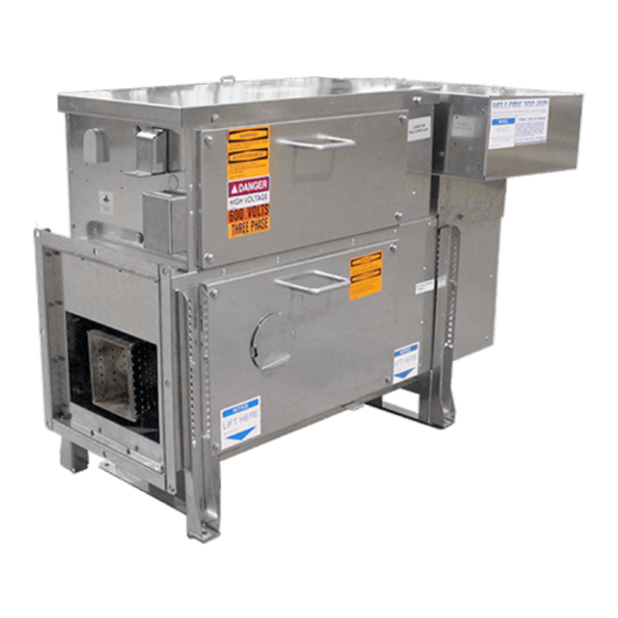
Motor/Impeller Assembly Rail Thermostat Locking Bar Temperature Control Optional Bolt-On Access Panel Optional Screw-On Leg Assembly Figure 2 – HELLFIRE 400 Gas Fired Blower Air Intake Hood Optional Low Intake Temperature Sensor Top Locking Bar Optional High Intake Toggle Switch... -
Page 5: Heater Overview
There are two versions of the device: 2.1 HELLFIRE 400 which puts out up to 400,000 BTU of heat. 2.2 HELLFIRE 900 which puts out up to 900,000 BTU of heat. -
Page 6: Gas Systems
GAS SYSTEMS HELLFIRE 400 Gas Train Gas Supply Inlet Manifold Gas Pressure Gauge Gas Supply Pressure Gauge Igniter Flame Rod Combination Gas Valve Burner Union Burner Defroster Burner Mounting Bracket HELLFIRE 900 Gas Train Regulator Vent Pilot Gas Solenoid Valve... -
Page 7: Gas Train Construction
The gas escapes through holes in a gas orifice by the porcelain bushing. manifold. Moisture can short-circuit the sensing circuit if – The flame rod length is 3” for the HELLFIRE 400 – water bridges the porcelain. and HELLFIRE 900. This can happen inside and outside the –... -
Page 8: Gas Regulator
Gas Regulator For both the HELLFIRE 400 and HELLFIRE 900, the Gas Regulator For both the HELLFIRE 400 and HELLFIRE 900, the manual shut-off valve comes standard, and required in the To maintain steady and correct flow for the gas to the... -
Page 9: Burner Defroster
Burner Defroster The burner defroster prevents moisture accumulation due to condensation and snow ingestion on the flame rod and igniter, while the heater is idle. HELLFIRE 400 - Burner Defroster Kit HELLFIRE 900 - Burner Defroster Kit... -
Page 10: Electronic Controls
ELECTRONIC CONTROLS Controller LED Descriptions LED Name Description State Indication TD, RD on and pulsing Heater in REMOTE SCADA mode. TX off and pulsing RS-485 TX off TD, RD, TX Heater in LOCAL AUTO mode. communications TD and RD on TD, TX off and pulsing 8N1 COM communications mode. -
Page 11: Fault Condition Codes And Led States
LED Name Description State Indication Thermostat closed. Heated air temperature ABOVE set point. High limit HIGH LIM thermostat High limit thermostat closed momentarily indicating air temperature Alternating exceeded set point. Manual MANUAL Selector switch in “MANUAL” position. Heater in MANUAL mode. operation Thermostat open. -
Page 12: Mode Selector Switch
HELLFIRE Controller Mode Selector Switch Electronic Controller Both the HELLFIRE 400 and HELLFIRE 900 units have The Controller provides the following functions: a mode selector switch, which has 3 modes: Monitors and controls the operation of the – ‘MANUAL’ allows for local operation of the heater. -
Page 13: Resets
Resets If the HELLFIRE shuts down because of an alarm condition, there are resets required to reset the heater. The resets are: Breaker Description Panel Breaker Most common required reset – (5 Amp) Open breaker to de-energize panel, then close to reset. –... -
Page 14: Hellfire 400 2014 Troubleshooting
HELLFIRE 400 2014 TROUBLESHOOTING **Reset controller only after observing the condition of all status * The resets made by aggressive retry function are not described indicators then follow reset instructions. in the conditions. Problem Conditions* Possible Cause Remedy** • Verify panel and motor breakers are closed. - Page 15 Problem Conditions* Possible Cause Remedy** Manifold pressure at • Increase manifold pressure to within Heater connected to natural natural gas limits. maximum for propane gas. gas. • The delivered heater is set for LPG. Duct system restricted. Gauge Clear blockage/debris from duct system. shows high back pressure when Heater operating Inspect tie duct and flex duct.
- Page 16 Problem Conditions* Possible Cause Remedy** • Verify supply pressure is within • Fan starts. nameplate rating. • Controller LEDs • Verify manual shutoff valve on top of Inadequate gas pressure. combination valve is open. Arrow in line – POWER on. with body. –...
- Page 17 Problem Conditions* Possible Cause Remedy** • Controller LEDs • Measure flame signal. • Marginal flame signal. – POWER on. • Inspect flame rod and wiring Dropping below 1.5 micro – MOTOR on. connections. amps. – HEAT on. • Replace any damaged items. –...
-
Page 18: Hellfire 900 2014 Troubleshooting
HELLFIRE 900 2014 TROUBLESHOOTING **Reset controller only after observing the condition of all status * The resets made by aggressive retry function are not described indicators then follow reset instructions. in the conditions. Problem Conditions* Possible Cause Remedy** • Verify panel and motor breakers are on. No LEDs are on. - Page 19 Problem Conditions* Possible Cause Remedy** • Controller LEDs – POWER on. • Wait for cycling switch to cool (closed). – MOTOR on. Cycling thermostat open. • Inspect cycling thermostat and wiring – RUN IND on. connections. Fan running. (Heater will operate for 10 –...
- Page 20 Problem Conditions* Possible Cause Remedy** • Fan starts. • Verify supply pressure is within nameplate rating. • Controller LEDs Inadequate gas pressure. • Verify pilot solenoid valve operation. – POWER on. • Verify manual pilot bulb valve is open. – MOTOR on. Handle in line with gas pipe.
- Page 21 Problem Conditions* Possible Cause Remedy** • Controller LEDs • Measure flame signal. Marginal flame signal PILOT – POWER on. • Inspect flame rod and wiring. and MAIN signal occasionally – MOTOR on. • Check crimp on connector for corrosion. drop below 1.2V. –...
-
Page 22: Hellfire 400 Maintenance
HELLFIRE 400 MAINTENANCE WARNING. Install and use Heater in accordance with WARNING. Risk of cutting fingers or hand. Disconnect owners manual and local codes. fan power prior to removing combustion chamber access panel or air intake. WARNING WARNING In the absence of local codes, installation must comply with CAN/CSA-B149 Installation code and National Fuel Gas Code ANSI Z223.1 / NFPA 54, or... -
Page 23: Motor/Impeller/Base Removal
Motor/Impeller/Base Removal The impeller is fitted with a taper lock bushing. To remove impeller from motor shaft: WARNING. Risk of cutting fingers or hand. Disconnect Clamp the motor and anchor the impeller using a fan power prior to removing combustion chamber suitable bar. -
Page 24: Burner Removal
Burner Removal Burner Defroster Removal The defroster circuit is protected with a reset-enabled NOTE: fuse. If tripped, open then close the panel breaker to reset. Turn heater OFF and disconnect power. Once impeller is at a complete stand still, remove combustion chamber access panel. -
Page 25: Hellfire 900 Maintenance
HELLFIRE 900 MAINTENANCE Thermostat Removal Remove cover from thermostat box to gain access to the thermostats. There are two thermostats. The high limit, which has a red and a white wire connected to it, and the cycling thermostat, which has a black and a blue wire, connected to it. -
Page 26: Flame Rod And Spark Igniter Removal
Flame Rod and Spark Igniter Removal Burner Defroster Removal The defroster circuit is protected with a reset-enabled NOTE: fuse. If tripped, open then close the panel breaker to reset. Turn heater OFF and disconnect power. If the flame rod (16) or spark igniter (15) requires inspection or replacement, remove them as follows: Once impeller is at a complete stand still, remove combustion chamber access panel. -
Page 27: Hellfire 400 Service
HELLFIRE 400 SERVICE WARNING. Risk of cutting fingers or hand. Disconnect WARNING. Install and use Heater in accordance with owners manual and local codes. fan power prior to removing combustion chamber access panel or air intake. WARNING WARNING In the absence of local codes, installation must comply with CAN/CSA-B149 Installation code and National Fuel Gas Code ANSI Z223.1 / NFPA 54, or... -
Page 28: Gas Supply Pressure
Gas Supply Pressure Dirt Trap And Strainer WARNING. All persons employed in handling propane WARNING. All persons employed in handling propane or natural gas shall be trained in proper handling and or natural gas shall be trained in proper handling and operating procedures, as required by local authorities operating procedures, as required by local authorities WARNING... -
Page 29: Vibration Specifications And Measurement
Vibration Specifications and Measurement Flame Signal All motor/impeller/base sets are match balanced with vibration levels lower than 0.20 in./sec RMS, at the four points depicted. Flame Signal Wire Connection, S1 Flame signal strengths: NOTE: GOOD - 3.0 or greater, fluctuating less than 0.5 micro amps DC WEAK –... -
Page 30: Air Switch
J.10 Air Switch The thermostat and the circuit can be individually tested as follows: Turn the mode selector switch “OFF”. Open the thermostat box located on the sensor duct. Disconnect the red and white leads of the high limit thermostat. Lowers set point At temperatures below 210 (410°F) the high limit... -
Page 31: Burner
J.14 Burner Drill out any blocked gas orifice using a #48 (.076) drill bit. J.15 Defroster GAS ORIFICE MIXING PLATES The defroster applies 25 watts of heat to the burner next to the flame rod and igniter. This is Visually inspect mixing plates for cracks or blockage. enough to raise the temperature of the end plate by Remove any blockages. -
Page 32: Hellfire 900 Service
HELLFIRE 900 SERVICE WARNING. Install and use Heater in accordance with WARNING. Do not attempt to manually light burner. owners manual and local codes. Heater equipped with an automatic electronic ignition system. WARNING In the absence of local codes, installation must WARNING comply with CAN/CSA-B149 Installation code and National Fuel Gas Code ANSI Z223.1 / NFPA 54, or... -
Page 33: Gas Supply Pressure
Gas Supply Pressure Dirt Trap And Strainer WARNING. All persons employed in handling propane WARNING. All persons employed in handling propane or natural gas shall be trained in proper handling and or natural gas shall be trained in proper handling and operating procedures, as required by local authorities WARNING operating procedures, as required by local authorities... -
Page 34: Vibration Specifications And Measurement
Vibration Specifications and Measurement As a further check, close the manual gas valve. The FLAME LED goes out, followed by the MAIN and All motor/impeller/base sets are match balanced PILOT LED, the red ALARM LED lights. Open manual with vibration levels lower than 0.20 in./sec RMS, at gas valves. -
Page 35: Air Switch Calibration
Remove the blockage and reset the controller. The Increase the manifold pressure to the maximum rated heater starts. setting. Once the air temperature exceeds the 216°C (420°F) set point, the controller removes the request for heating, HEAT LED off, indicates alarm with STATUS LED red, FSR ALARM LED red, ALARM LED red and HIGH LIM LED alternating. -
Page 36: Burner
K.15 Burner K.16 Defroster Ignitor Flame Rod Gas Orifice The defroster applies 30 watts of heat to the burner next to the flame rod and igniter. This is Mixing Plates enough to raise the temperature of the end plate by approximately 90°F. It can be difficult to tell it is Visually inspect mixing plates for cracks or blockage. -
Page 37: Hellfire 400 Parts
HELLFIRE 400 PARTS Parts - Heater Body Table 1 – Heater Body Parts List Index Part No. Description Index Part No. Description 17436-02 LOCKING BAR, FRONT 13746 LID, ELECTRICAL COMPARTMENT 16685 LVL LEG ASSY, HF900/400, SCREW 17436-03 LOCKING BAR, TOP 16076 LEG, FRONT, HF400/900, BOLT ON 16679 EXT, INTAKE W/SCREEN, 13”H HF400... -
Page 38: Parts - Control Panel, 240V Single Phase
Parts - Control Panel, 240V Single Phase Table 1 – Control Panel Parts List Index Part No. Description Index Part No. Description 9078-0043 CONTACTOR, DEFINTE PURPOSE, 2 POLE, 9038-0067 SW TOGGLE, DPDT ON-OFF-ON, SCREW TERM 25AMP, 3HP, 1PH 9042-0044 CB, 1 POLE 5 A 9078-0044 PROTECTIVE COVER, CONTACTOR,2 POLE 9042-0046 CB, 2 POLE 32 A DIN RAIL MNT 9079-0004 RCPT, DUPLEX 15A-125V, GFCI SMARTLOCK... -
Page 39: Parts - Control Panel, 460 - 575V Three Phase
Parts - Control Panel, 460 - 575V Three Phase Table 1 – Control Panel Parts List Index Part No. Description Index Part No. Description 9078-0126 CONTACTOR, 12A C/W 120V COIL 9038-0067 SW TOGGLE, DPDT ON-OFF-ON, SCREW TERM 9088-1001 STOP, END, PLASTIC, 10MM W, DIN RAIL 9040-0150 THERMAL OVERLOAD RELAY, 1.0 - 5.0 A, 3PHASE 17968 TB, TUBULAR, 6 POLE 9042-0044 CB, 1 POLE 5 A... -
Page 40: Parts - Gas Components
Parts - Gas Components Table 1 – Gas Components Index Part No. Description 9069-1020 GAUGE, PRESS, 0-30"WC 1/8NPT 14970 IGNTR, SPARK GENERAL, COATED W/BORON 14978 ROD, FLAME 3"L 1/4"NPT 15165-05 CABLE ASSY, FLAME ROD 22"L P/NG HF400 16659 BRKT, BURNER, HF400 COMB CHMBR 16729 BURNER ASSY, 400 KBTU/HR 16984... -
Page 41: Hellfire 900 Parts
HELLFIRE 900 PARTS Parts - Heater Body Table 1 – Heater Body Parts List Index Part No. Description Index Part No. Description 17439-XX MOT/IMPLR ASSY 18929 LID, ELECTRICAL COMPARTMENT HF900 240VAC 1PH 17437-01 LOCKING BAR, TOP HF900 208/230/460VAC 3PH 16058 PLENUM, INTAKE, HF900 HF900 575VAC 3PH 16075 LEG, REAR, HF400/900 17437-02 LOCKING BAR, FRONT... -
Page 42: Parts - Control Panel, 240V Single Phase
Parts - Control Panel, 240V Single Phase Table 1 – Control Panel Parts List Index Part No. Description Index Part No. Description 9077-0034 CB, 1A, PNL MNT 9012-0059 BUCHANAN TSB100012DS=TUBULAR BARRIER ST 9077-0035 CB, 15A, PNL MNT 9040-0018 RELAY, FS, BURNER CONTROL 9078-0043 CONTACTOR, 2 POLE, 25A, 120V COIL 9040-0022 AMPLIFIER, FS, MDL 9078-0044 PROTECTIVE COVER, CONTACTOR,2 POLE... -
Page 43: Parts - Control Panel, 460 - 575V Three Phase
Parts - Control Panel, 460 - 575V Three Phase Table 1 – Control Panel Parts List Index Part No. Description Index Part No. Description TRFRMR, CONT 460/575>120V 15A/24V 4A (shown) 9012-0059 BUCHANAN TSB100012DS=TUBULAR BARRIER ST 9064-0033 (for configurations with 120V duplex receptacle) 9040-0018 RELAY, FS, BURNER CONTROL TRFRMR, CONT 460/575>120V 4A /24V 4A 9064-0031... -
Page 44: Parts - Gas Components
1,16 Parts - Gas Components Table 1 – Gas Components Index Part No. Description Index Part No. Description 11700 BURNER, HF900 19304 HTR, 2”DIA 30W 24VAC 18”L LEADS SI 11712 VENT ELBOW 9045- CONN, 1/4TUBE MALE * 1/8NPTM, BR 11739 BRKT, SUPPORT, HF 900 BURNER 0085 14978 ROD, FLAME 3”L 1/4”NPT 9045-0160 VALVE, BALL 1/4”... -
Page 45: Electrical
ELECTRICAL Motor Resistances Motor Item Description Nominal High HF9016-0001 MOTOR, 7.5HP 575V 60HZ 3PH 3525RPM 1.73 1.64 1.82 HF9016-0002 MOTOR 7.5HP 208/230/460V 60HZ 3PH, 3600 1.14 1.08 1.20 HF9016-0003 MOTOR, 7.5HP 240V 60HZ 1PH 3450RPM 0.98 0.93 1.03 HF9016-0007 MOTOR 5 HP 240V 60HZ 1PH 3450RPM 0.91 0.86 0.96... -
Page 46: Transformer Resistances
Transformer Resistances Transformer Item Description Nominal High HF9064-0009 TRFRMR, 120/24VAC 40VA 120v Primary 21.7 20.62 22.79 24V secondary 0.69 0.66 0.72 HF9064-0028 TRFRMR, CONT 460/575 240V 100VA 480V Primary 16.80 15.96 17.64 600V Primary 22.63 21.50 23.76 240V secondary 10.90 10.36 11.45 HF9064-0030... -
Page 47: Hellfire 400 Wiring Schematics
HELLFIRE 400 Wiring Schematics... -
Page 53: Hellfire 900 Wiring Schematics
HELLFIRE 900 Wiring Schematics... -
Page 59: Appendix A - Hellfire Unit Maintenance Checklist
APPENDIX A - HELLFIRE UNIT MAINTENANCE CHECKLIST Location Name Date of Maintenance Switch No. Maintenance Done By Hour Meter Reading Model No. Site Photos (File #) Serial No. HELLFIRE Unit & Ducting System Maintenance Checklist The intent of this checklist is to provide the user with a detailed and summarized method to The intent of this checklist is to provide the user with a detailed and summarized method to perform service and maintenance on the HELLFIRE unit and ducting system. - Page 60 HEATER MAINTENANCE Label Label Burner Electrical control access panel Regulator vents Air intake plenum Condensation vent Leveling leg Gas manifold Control panel Control cabinet lid Motor/Impeller/Base Air intake hood Combustion chamber access panel Air intake extension Track duct mounting bracket Identification tag Mode selector switch Preventative Maintenance Grid...
- Page 61 Check impeller for any visible damage. During a motor run test, make note of any excessive vibration or bearing noise. For additional motor specifications, refer to Motor Section K.7 to K.8 for HELLFIRE 900 and Section J.7 to J.8 for HELLFIRE 400 in the heaters Installation, Operation & Maintenance Instructions. Access panel gaskets...
- Page 62 Label Label Track duct Flex duct Track duct deflector Track duct elbow Tie duct Rail mounting spring clip and pad Point nozzle Ballast retainer Track duct mounting bracket Transition duct Sensor duct Square to round adapter TIE DUCT/CROSS DUCT MAINTENANCE Preventative Maintenance Grid Cells of the grid with check boxes ( ‘X’...
- Page 63 TRACK DUCT MAINTENANCE Preventative Maintenance Grid Cells of the grid with check boxes ( ‘X’ ) inside are the minimum maintenance measures required to be performed at the indicated time periods. Annual Every 2 Every 6 Inspect Action Start-Up Months Months Track duct mounting Visually inspect the track ducts and point nozzles damage and...
- Page 64 Spare Parts Installed During Inspection Description Part # Description Part # Required Additional Spare Parts (To be shipped at a later date) Description Part # Description Part # Comments...
- Page 65 NOTES NOTES...
- Page 66 NOTES NOTES...
- Page 67 NOTES NOTES...
-
Page 68: Warranty
PLEASE ADHERE TO INSTRUCTIONS IN THIS MANUAL WARRANTY Failure to do so may be dangerous and may void certain provisions of your warranty. For further assistance, please call 1.855.244.3128 WARRANTY warranty applies paint fi nishes except Under normal use the Company manufacturing defects apparent within 30 days from the warrants to the purchaser that defects in material date of installation.
Need help?
Do you have a question about the HELLFIRE 400 and is the answer not in the manual?
Questions and answers