Table of Contents
Advertisement
Quick Links
IMPORTANT INSTRUCTIONS - SAVE THESE INSTRUCTIONS
Read all instructions before installing or using the heater. Please adhere to instructions published in
this manual. Failure to do so may be dangerous and may void certain provisions of your warranty.
Gas Fired Railway Switch Heater
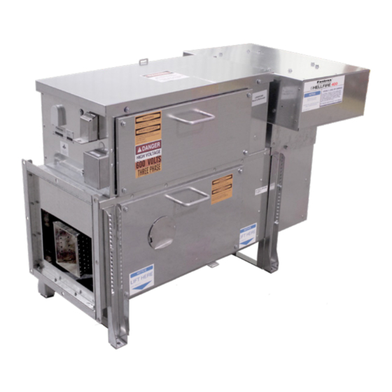
HELLFIRE 400
Installation, Operation, & Maintenance Instructions
ANSI Z83.7-2017 / CSA 2.14-2017
Gas Fired Unvented Construction Heaters (Unattended Type)
Fastrax
is a registered trademark of Thermon
®
Copyright
2022. All rights reserved.
©
Part No. HF17811.Rev.4.00
January 2022 Printed in Canada
ISO 9001
Advertisement
Table of Contents

Related Manuals for Thermon HELLFIRE 400


Summary of Contents for Thermon HELLFIRE 400
- Page 1 HELLFIRE 400 Installation, Operation, & Maintenance Instructions ANSI Z83.7-2017 / CSA 2.14-2017 Gas Fired Unvented Construction Heaters (Unattended Type) Fastrax is a registered trademark of Thermon ® Part No. HF17811.Rev.4.00 January 2022 Printed in Canada Copyright 2022. All rights reserved.
-
Page 2: Table Of Contents
TABLE OF CONTENTS A. Important Notices And Warning Symbols E.18 Reset ....................18 E.19 Energy Management System (EMS) ......19 B. Identification E.20 Terminal Blocks ..............20 B.1 Heater Labels ................6 E.21 Inputs and Outputs ............20 B.2 Model and Serial Number Tag ........6 F. Troubleshooting B.3 Components Diagram ............7 B.4 ... - Page 3 J. Service J.1 Recommended Service Schedule ......45 J.2 Gas Supply Pressure ............46 J.3 Gas Supply Leak Test ............46 J.4 Manifold Leak Test ............46 J.5 Combination Gas Valve Seat Leak Test ....46 J.6 Dirt Trap And Strainer ............. 46 J.7 Motor ....................47 J.8 Vibration Specifications and Measurement ..47 J.9 ...
-
Page 4: Important Notices And Warning Symbols
IMPORTANT NOTICES AND WARNING SYMBOLS Keep this manual with the machine at all times. The purpose of this manual is to provide owners, operators, and installers with the precautions and procedures essential for the safe and proper operation for its intended purpose. CAUTION. This symbol indicates a potentially hazardous situation, which, if not avoided, may result in personal injury or damage to the CAUTION equipment. WARNING. This symbol indicates an imminently hazardous situation, which, if not avoided, can result WARNING in serious injury or damage to the equipment. - Page 5 Description Symbol English French Risque d’incendie, de brûlures, d’inhalation et Fire, burn, inhalation, and explosion hazard. Keep d’explosion. Garder les combustibles solides, tels solid combustibles, such as building materials, les matériaux de construction, le papier et le carton, paper, or cardboard, a safe distance away from the à bonne distance de ce radiateur, comme il est heater as recommended by the instructions. Never recommandé dans les instructions. Ne jamais utiliser use the heater in spaces which do or may contain cet appareil dans des endroits qui contiennent ou volatile or airborne combustibles, or products such pourraient contenir des combustibles volatiles ou en as gasoline, solvents, paint thinner, dust particles or suspension dans l’air tels l’essence, les solvants, les unknown chemicals.
-
Page 6: Identification
IDENTIFICATION B.1 Heater Labels Each heater has a ratings label, a logo label, a model The logo, located on the side of the air intake hood and serial number tag and a voltage label. identifies the series as HELLFIRE, and the size, either 400 or 900. The ratings label contains all identification and safety information. It is fastened by a lanyard and stored in The model / serial number tag is a blue aluminum the manual pocket inside the control enclosure next plate. -
Page 7: Components Diagram
B.3 Components Diagram The following component names are referred to in this manual. See Section L - Parts for part numbers and ordering. Label Label Label Track duct Gas manifold Transition duct Track duct elbow Control cabinet lid Sensor duct Rail mounting spring clip and Air intake hood Square to round adapter ... -
Page 8: Gas Manifold Diagram
B.5 Gas Manifold Diagram Label Label Burner Gas supply pressure gauge Defroster Gas supply inlet Flame rod Burner mounting bracket Igniter Union Manifold gas pressure gauge Combination gas valve... -
Page 9: Pre-Operation Inspection
PRE-OPERATION INSPECTION C.1 Important Notices To ensure trouble free operation during the winter months, Perform inspection and operations in accordance with NOTE: inspect the system annually at the start of the season. the instructions provided in the service section of this manual. WARNING. All persons employed in handling This inspection guide assumes that all applicable NOTE: propane or natural gas shall be trained in proper... - Page 10 Inspect Action Verify propane tank is filled, or natural gas service is open and has pressure. Gas source Open all manual gas shut off valves and inspect all gas lines for leaks. Electrical service Verify electric service power is on. Close supply circuit breakers. Verify correct line voltages at each heater. Must be within +/- 5% of nominal voltage. Electrical supply Verify current draw is less than or equal to nameplate rating. Verify supply and manifold gas pressures are within nameplate limits when Gas supply heater and all connected loads are operating. Verify flame signal strength is stable (+/- 0.5) and between 3.0 and 8.0 micro amps DC. If signal strength is low: Flame signal strength Clean or replace flame rod.
-
Page 11: Operation
OPERATION D.1 Introduction D.3 Start-Up Sequence (All Modes) The switch heater is a gas fired, hot air heating system Once a start request is received the control sequence begins. that keeps a turnout clear of ice and snow during If the controller is in ‘REMOTE RTC’ mode then it waits NOTE: winter storms by blowing hot air, between the stock for the ‘DELAY START’ time before initiating. rail and moving points, at the tie plates on which the points slide, and at the gage rods. Table 1 – All Modes Conditions/Sequence Status LED D.2 Modes Heater is in an operational mode not OFF. -
Page 12: Heat Output Adjustment
D.5 Heat Output Adjustment Depending on the length of switch points, its’ WARNING. Do not operate above maximum priority, local climate conditions, and experience, the manifold pressure as this can produce carbon operator can increase or decrease the heat output monoxide in excess of maximum allowable of 0.08 accordingly. The recommended heat output is in the WARNING air free carbon monoxide (AFCO). -
Page 13: Controls & Indications
CONTROLS & INDICATIONS E.1 AAR Signal Wiring - For non SCADA installations Table 1 – AAR Signal Wiring Terminals Label Description A contact closure across these terminals starts the heater when the heater is in REMOTE RTC A1 - A2 REMOTE START mode. A3 - A4 Dry contact closes to provide a run indication. A5 - A6 ALARM Dry contact closes to provide alarm indication. Default is closed. If FORCE OFF function is desired, remove shorting link and replace with A7 - A8 FORCE OFF customer supplied relay contact. -
Page 14: Controls
E.3 Controls Power: This switch turns the power supply to the limit, the heater turns off, and the run indication is board ‘ON’ or ‘OFF’. maintained as long as the heater is requested. Timer is reset once the RTC request is removed. RTC WARNING. TB1 and TB2 120Vac inputs to controller can then request the heater for another cycle. can remain energized. It is intended to save fuel by avoiding unnecessary WARNING heater operation by the dispatcher. This setting is true for RTC MODE only. Under MANUAL, AUTO, and ... -
Page 15: Terminal Blocks
LED Name Description State Indication FSR Reset Controller clears DSI control module alarm. EMS module request for heater to run. Heater only acts on this request if in AUTO mode. EMS REQ EMS request Local EMS mode. Installed EMS module can request heater operation Pulsing ON or OFF. POWER Power supply Controller energized. MOTOR Motor Contactor closed, motor turned on. Controller request DSI control module requested. Ignition sequence started or burner HEAT for heat operating. Heater run Indication contact closed. Turns on after 60 seconds of normal RUN IND indication operation. -
Page 16: Data Communications
E.6 Data Communications E.8 Activating a COMMUNICATION Parameter The RS-485 serial communications port, and Read and understand the following procedure before NOTE: an EEPROM, allows the heater to be part of a starting. COMMUNICATION parameters require a Supervisory Control and Data Acquisition (SCADA) hardware programming key to make changes, MODE network and Remote Control and Monitoring System parameters do not. (RCMS) software. Toggle mode selector switch to “OFF”. If installed, The RS-485 port runs at 9600 baud and allows disconnect EMS cable from controller. Plug communication over long distances of up to 1000’ programming key into the mating EMS 10-pin ... -
Page 17: Activating Mode Parameter
E.10 Activating MODE Parameter E.13 RAIL THERMOSTAT Mode, Normal With the introduction of the 2014 model Hellfire, Read and understand the following procedure before NOTE: the rail thermostat operation was reversed. The starting. thermostat now opens when cold and closes when The controller must be powered on for a minimum of warm. -
Page 18: Aggressive Retry Feature
Table 1 – Fault Condition Codes and LED States Prior to performing a reset: WARNING. If you smell gas; Immediately Code Alarm Fault Condition State extinguish all sources of ignition and turn off gas Type source. WARNING Minor Selector switch ENABLE Dark Call qualified service technician to repair leak. -
Page 19: Energy Management System (Ems)
E.19 Energy Management System (EMS) When snow is no longer sensed the heater request is held for the duration of the timer. If Adding the EMS allows a heater to operate at any time during the delay snow is sensed the automatically, or to act as a weather station when part timer is reset. of a network of heaters controlled by the Fastrax® TEST: RCMS. This switch simulates precipitation when ON. The system includes a module, a precipitation Used to test the module operation. detector, ambient temperature sensor, and rail thermostat. Once installed, the controller recognizes SENSITIVITY: the EMS module and works in conjunction with it. -
Page 20: Terminal Blocks
E.20 Terminal Blocks E.21 Inputs and Outputs The controller interconnects with the control panel PRECIPITATION DETECTOR: As its name implies, it by means of 2 board level headers, TB-1 and TB-2, senses precipitation that can be in the form of rain which accept wire harness plug connectors. or snow. The controller and EMS module connect via a ribbon Snow landing on the detector’s heated sensing head cable that plugs into the 10-pin header found on each. melts to form water drops. The 360° sensing surfaces ... -
Page 21: Troubleshooting
TROUBLESHOOTING * The resets made by aggressive retry function are not **Reset controller only after observing the condition of all described in the conditions. status indicators then follow reset instructions Problem Conditions* Possible Cause Remedy** Verify panel and motor breakers are ࢦ closed. No LEDs are on. No line power. Verify supply voltage at power ... - Page 22 Problem Conditions* Possible Cause Remedy** The as delivered heater is set for LPG Manifold pressure at Heater connected to natural operation. Increase manifold pressure to maximum for propane. gas. within natural gas limits. Service burner. ࢦ Corrosion, dirt or other debris Heater operating Drill out each orifice with #48 drill Manifold pressure ࢦ restricts burner orifii.
- Page 23 Problem Conditions* Possible Cause Remedy** Fan starts, runs ࢦ Heater NOT connected to Complete heater installation. briefly then stops. duct system. Controller LEDs ࢦ Clear intake screen of blockage, – POWER on. Air intake severely blocked. i.e. ice, snow, paper. – ALARM red. Calibrate air switch. Air switch fails to close when – AIR SW fan operating.
- Page 24 Problem Conditions* Possible Cause Remedy** Marginal flame signal. Inspect flame rod and wiring. Replace any damaged items, fouled rod, corroded Signal drops below 1.5 micro wire or cracked boot. amps. Manifold gas pressure set Reduce gas pressure to within nameplate too high. setting. Fan starts. ࢦ Controller LEDs ࢦ Heater cycles Air intake blocked. Clear intake screen. –...
-
Page 25: Installation
INSTALLATION G.1 Overview WARNING. Install and use Heater in accordance The following are general guidelines for the installation of with owners manual and local codes. typical HELLFIRE gas fired systems. They should be followed WARNING In the absence of local codes, installation must in conjunction with the specific site layout drawings provided comply with CAN/CSA-B149 Installation code with each heater. and National Fuel Gas Code ANSI Z223.1 / NFPA 54, or Standard for the Storage and Handling of ... - Page 26 Figure 2 - 140” Clearance Figure 3 - 155” Clearance 26 26...
- Page 27 Figure 4 - Clearance, Turned 90 Degrees...
-
Page 28: Site Preparation
G.6 Gas Supply Piping and Minimum Pressure Drop mitigation efforts can only be effective if ALL external remote circuits connecting to the switch heater have been protected WARNING. -
Page 29: Power Connections
Grounding of the switch heater metal housing as ࢦ well as the ground terminals of the primary arresters is essential for personnel protection as well as surge protection. Grounding rods and conductors must be installed in accordance with the AREMA Signal Manual of Recommended Practice. Primary surge protection must be installed in accordance ࢦ... - Page 30 Conductor Sizing Using the following table to aid in the selection of the appropriate size conductors between the heater and service. Table 1 – Conductor Sizing Wire Size Maximum Distance 1110 1764 2806 1360 4462 1048 1668 2650 1285 4215 2043 6702 1430...
-
Page 31: Thermostat Installation
G.9 Thermostat Installation As received panel with no EMS module. Install the thermostat sensor box as per instructions below: Remove combustion chamber shipping cover. Detach thermostat box from shipping cover. Secure thermostats to the duct using SST machine screws - ensure colour coded wires match. Secure thermostat box to the sensor duct as depicted, with the ground wire under the head of a bolt and washers. - Page 32 Ambient Temperature Sensor Remove wire through cover and route cable to a point directly beneath the EMS module. Insert To route the sensor cable it is necessary to remove the connector into mating receptacle. air intake. Remove the 4 screws holding the extension to the elbow. Leave the hood and extension fastened together.
- Page 33 Pass the two (2) wires from the rail temperature sensor through the hole, install the locknut and tighten. Rail Thermostat Mount the rail thermostat on the field or gage side Insert, one each of the bared wires into the of the stock rail ahead of the points and tie duct, two terminals on the surge suppression circuit as shown. Select a location shaded from the sun. board, and tighten. There is no polarity. Provide strain relief in the cable, by leaving adequate slack, as shown, to allow for rail pumping. Replace the cover, and tighten the four (4) Phillips screws. Connect the surge isolator two pin connector with the mating plug located inside the electrical Remove the yellow shim washers when installed on 115 component area, hanging immediately under ...
-
Page 34: Inspection And Commissioning
Gas System G.11 Inspection and Commissioning Supply pressure at rated supply pressure with all … Once the installation is complete review it against the connected loads operating. following checklist. Gas supply leak tested. … Point Nozzles Heater Installed. … Level. …... -
Page 35: Heater Specifications
HEATER SPECIFICATIONS H.1 Performance H.5 Controls Table 1 – Controls Clears ice and snow from switches with up to 28-foot ࢦ points or longer. (Recommended heating, 10,000 to Feature Description 22,500 BTU/hr per foot of track coverage, based on severity of local climate). Provide dry contract, rated for 24Vac Remote Start 0.5 amp 1500 scfm of heated air delivered via a duct system, point ࢦ Run and Alarm Indication nozzles and track duct vents. -
Page 36: Controller Terminal Identification
H.8 Controller Terminal Identification Table 1 – Controller Terminal Identification Terminal Input Output Power Source Block 120Vac 120Vac Neutral 120Vac Motor Contactor 120Vac Neutral 120Vac 120Vac Transformer 120Vac Neutral 120Vac 120Vac 120Vac FSR Request 120Vac 24Vac 24Vac From Transformer 24Vac 24Vac From Transformer Run Indication Dry Relay Contact Run Indication Dry Relay Contact Alarm Indication Dry Relay Contact Alarm Indication Dry Relay Contact... -
Page 37: Schematics
H.9 Schematics... - Page 41 41 41...
- Page 42 42 42...
-
Page 43: Maintenance
54, or Standard for the Storage and Handling of Liquefied Petroleum Gases, ANSI / NFPA 58. caution when in close proximity. WARNING For outdoor use only. For use with ductwork only. Only duct work supplied by Thermon Heating Systems shall be WARNING. Burn hazard / hot surfaces. Do not used with the heater. Minimum clearance from touch track ducts, nozzles or any non-insulated combustibles: 2 inches. duct connected downstream of heater during... -
Page 44: Motor/Impeller/Base Removal
To install the impeller, reverse sequence except step 4. Install replacement motor/impeller/base assembly, following reverse order. I.4 Flame Rod and Spark Igniter Removal I.3 Impeller Removal Motor/impeller sets not match balanced by Thermon NOTE: Heating Systems void future warranty claims. Replacement of motor or impeller only. Dynamically NOTE: balance the motor/impeller and base assembly to If the flame rod (3) or spark igniter (4) requires inspection or ... -
Page 45: Burner Removal
I.5 Burner Removal Remove burner. Reverse procedure to reinstall. I.6 Burner Defroster Removal The defroster circuit is protected with a reset-enabled NOTE: fuse. If tripped, open then close the panel breaker to reset. Turn heater OFF and disconnect power. Turn heater OFF and disconnect power. Once impeller is at a complete stand still, remove combustion chamber access panel. Once impeller is at a complete stand still, remove ... -
Page 46: Gas Supply Pressure
If a gas leak is detected, turn heater “OFF”. Replace any cracked fittings or components, tighten any leaking pipe connection, or disassemble, reapply pipe thread sealant, and reassemble. J.5 Combination Gas Valve Seat Leak Test Turn heater OFF. Verify supply pressure is between 14 – 20 inches water column. Close the manual shut off on top of valve (7). Close the supply manual shutoff external to heater, typically mounted on the gas line riser. After 10 minutes there should be no decrease of pressure on the supply pressure gauge. -
Page 47: Motor
J.7 Motor J.9 Lubrication Running amps greater than 115% of the motor rated full load The motor has sealed bearings and does not require amps can indicate failed bearings, excessive air leaks in the lubrication. ductwork, inadequately sized power supply wires, or poor When installing flame rod or igniter always apply high electrical connections. temperature anti seize compound to threads. Voltage Phase Motor FLA Rating* FLA X 1.15** J.10 Direct Spark Ignition Control Module (DSI) This module has no serviceable parts. To replace, disconnect the flame rod and ignition ... -
Page 48: Flame Signal
J.11 Flame Signal J.12 Air Switch To check the air switch operation, while operating the unit, block 80% of the air intake screens Flame signal strengths: NOTE: openings with a sheet of cardboard. The heater GOOD - 3.0 or greater, fluctuating less than 0.5 micro continues to operate. amps DC Now block 90%. The DSI extinguishes the burner and WEAK – between 0.8 and 2.9 micro amps and / or indicates alarm with the “FSR ALARM” LED lit. ... -
Page 49: Aar Terminals, Signals, And Communications
J.15 AAR Terminals, Signals, and Communications To correct the problem, remove the burner, flame rod and igniter, following the removal instructions in the To verify REMOTE START: maintenance section. Place the heater in REMOTE RTC mode, and Drill out any blocked gas orifice using a #48 (.076) drill bit. make a contact closure across AAR terminals A1 A2. The heater starts after the delay on period. To verify RUN indication: Measure continuity across AAR terminals A3 A4. Closed contact indicates run, open indicates stopped. Confirm against actual heater state. To verify ALARM indication: Measure continuity across AAR terminals A5 A6. Closed contact indicates alarm, open indicates normal operation. Confirm against actual heater ... -
Page 50: Parts
PARTS K.1 Parts - Heater Body Table 1 – Heater Body Parts List Index Part No. Description Index Part No. Description 13746 LID, ELECTRICAL COMPARTMENT 16685 LVL LEG ASSY, HF900/400, SCREW 17436-03 LOCKING BAR, TOP 16076 LEG, FRONT, HF400/900, BOLT ON 16679 EXT, INTAKE W/SCREEN, 13”H HF400 17344 BOX, TOGGLE SW LOCK OUT 16679-04 EXT, INTAKE W/SCREEN, 43”H HF400 9038-0057 SW TOGGLE, SPDT ON-OFF-ON 16680 HOOD, INTAKE, HF400, 26.5*18.18”W 9038-0060 SW BOOT, BLACK NEOPRENE 16426... -
Page 51: Parts-Control Panel, 240V Single Phase
K.2 Parts-Control Panel, 240V Single Phase Table 2 – Control Panel Parts List Index Part No. Description Index Part No. Description 9038-0067 SW TOGGLE, DPDT ON-OFF-ON, SCREW TERM 9078-0044 PROTECTIVE COVER, CONTACTOR,2 POLE 9042-0044 CB, 1 POLE 5 A 9079-0004 RCPT, DUPLEX 15A-125V, GFCI SMARTLOCK 9042-0046 CB, 2 POLE 32 A DIN RAIL MNT 9088-1001 STOP, END, PLASTIC, 10MM W, DIN RAIL 9043-0004 BLOCK, TERM AAR 12 POLE C/W HDW 17968 TB, TUBULAR, 6 POLE 9043-0025 BLOCK, TERM 4 POLE, 600V 115A 18532 LABEL, AAR CONNECTOR, VINYL 9043-0027... -
Page 52: Parts - Control Panel, 460-575V Three Phase
K.4 Parts - Control Panel, 460-575V Three Phase Table 4 – Control Panel Parts List Index Part No. Description Index Part No. Description 9038-0067 SW TOGGLE, DPDT ON-OFF-ON, SCREW TERM 9077-0034 CIRCUIT BREAKER, 1 AMP, PANEL MOUNT 9040-0150 THERMAL OVERLOAD RELAY, 1.0 - 5.0 A, 3PHASE 9078-0126 CONTACTOR, 12A C/W 120V COIL 9042-0044 CB, 1 POLE 5 A 9088-1001 STOP, END, PLASTIC, 10MM W, DIN RAIL 9042-0049 (For 460V) CB, 3 POLE 13A 17968 TB, TUBULAR, 6 POLE 9042-0071 (For 575V) CB, 3 POLE 13A 18532... -
Page 53: Parts - Gas Components
K.6 Parts - Gas Components Table 6 – Gas Components Index Part No. Description Index Part No. Description 9069-1020 GAUGE, PRESS, 0-30"WC 1/8NPT 17450 VALVE, GAS CONTROL, DIRECT SPARK IGN 14970 IGNTR, SPARK GENERAL, COATED W/BORON 17981 HEATER, SURF. MNT. 30W, 24VAC W/ LEADS 14978 ROD, FLAME 3"L 1/4"NPT 19033 CABLE ASSY, IGN 17"L P/NG HF400 2014, FENWAL 15165-05 CABLE ASSY, FLAME ROD 22"L P/NG HF400 Note: This list identifies the major components only. Recommended spare parts highlighted red. 16659 BRKT, BURNER, HF400 COMB CHMBR 16729 BURNER ASSY, 400 KBTU/HR 16984... - Page 54 NOTES...
- Page 55 NOTES...
- Page 56 PLEASE ADHERE TO INSTRUCTIONS IN THIS MANUAL Failure to do so may be dangerous and may void certain provisions of your warranty. For further assistance, please call 1.855.244.3128 WARRANTY No warranty applies to paint fi nishes except for Under normal use the Company manufacturing defects apparent within 30 days from the warrants to the purchaser that defects in material date of installation.
Need help?
Do you have a question about the HELLFIRE 400 and is the answer not in the manual?
Questions and answers