
Related Manuals for Artila Matrix-704


Summary of Contents for Artila Matrix-704
- Page 1 Matrix-704 Linux-Ready Cortex-A5 Industrial IoT Gateway Hardware Guide Version: 1.1 2024 January Copyright © Artila Electronics Co., Ltd. All Rights Reserved.
- Page 2 Matrix-704 Hardware Guide Trademarks The Artila logo is a registered trademark of Artila Inc. All other trademarks or registered marks in this manual belong to their respective manufacturers. Disclaimer Information in this document is subject to change without notice and does not represent a commitment on the part of Artila.
- Page 3 Matrix-704 Hardware Guide Document Amendment History Revision Date Remark V1.0 2020 June Initial V1.1 2024 Jan. Information updated ARTILA...
-
Page 4: Table Of Contents
Matrix-704 Hardware Guide Table of Contents Introduction ....................5 Features ....................5 Specifications (Hardware)................ 5 Specifications (Software) ................. 6 Packing List ..................... 7 Optional Accessory.................. 7 Layout ......................8 Connector & LED Indicator ..............8 Dimensions....................9 Pin Assignment and Definitions ..............10 Multi-function Reset Button .............. -
Page 5: Introduction
Matrix-704 Hardware Guide 1. Introduction Matrix-704 based on ARM Cortex-A5, is a Linux-ready IoT gateway with highly integrated and low power consumption. Matrix-704 is a reliable industrial IoT gateway with Surge-protected RS-485 serial ports that secure the data transmission to increase system reliability in a wide range of demanding industrial applications. -
Page 6: Specifications (Software)
Matrix-704 Hardware Guide Console / Debug Ports • Support micro-USB console port • Serial console port (inside the box) Serial Ports • 4 x RS-485 ports • Signal: Data+, Data- • Baud Rate: Up to 921.6Kbps • Surge-protected design SD Slot •... -
Page 7: Packing List
Please refer to “M-A5D35” system on module information for software operating & utility at following: http://www.artila.com/download/A5D35/Linux/ 1.4 Packing List Matrix-704: Linux-ready Cortex-A5 536MHz Industrial IoT Gateway with 512MB SDRAM, 16GB eMMC Flash with four Surge-protected RS-485 serial ports 1.5 Optional Accessory ... -
Page 8: Layout
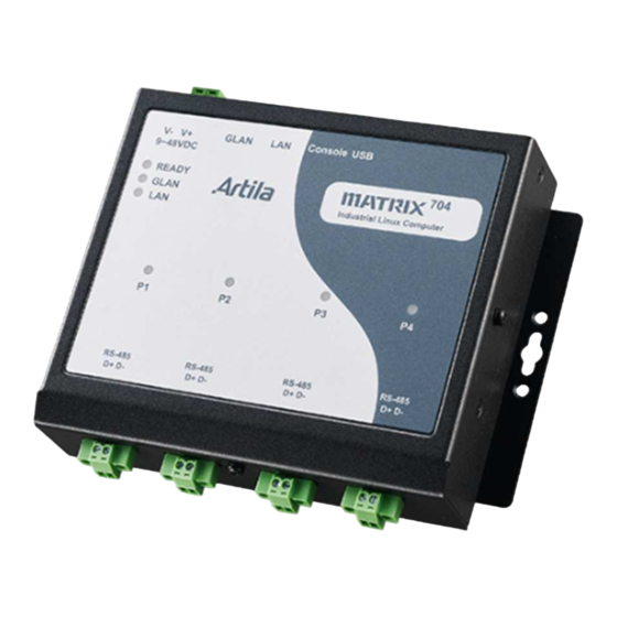
Matrix-704 Hardware Guide 2. Layout 2.1 Connector & LED Indicator Power Input GLAN LAN CONSOLE USB HOST 2.0 Ready LED GLAN LED LAN LED Serial Port LED COM1 ~ 4 (RS485) ARTILA... -
Page 9: Dimensions
Matrix-704 Hardware Guide 2.2 Dimensions Unit: mm Mounting hole: M3 Screw ARTILA... -
Page 10: Pin Assignment And Definitions
3. Pin Assignment and Definitions 3.1 Multi-function Reset Button The Matrix-704 provides a multi-function reset button located on the right side of the chassis shown below: The behavior of the reset button depends on how long you press the reset button. -
Page 11: Led Indicators
Matrix-704 Hardware Guide 3.2 LED Indicators The LED provides the Matrix-704 operation information. The LED status is described as follow: “Ready” (Ready LED indicator): Ready LED will turn on in green color while power is properly supplied. After system is ready for operation, Ready LED will keep in solid orange color and a beep will be heard ... -
Page 12: Serial Port (Rs-485)
The Matrix-704 provides on-board 120Ohm termination resistor for each RS-485 port. The default mode is “Disabled” the Termination Resistor (no Jumper-setting) To enable the termination resistor, please remove the upper cover of the Matrix-704, and add jumper-setting that inside the packing. ARTILA... -
Page 13: Power Connector
Matrix-704 Hardware Guide 3.4 Power Connector Connecting +9 ~ +48VDC power line to the Power in terminal block. In the meantime, Ready LED will turn on in green color while power is properly supplied. After system is ready for operation, Ready LED will keep in solid orange color and a beep will be heard. -
Page 14: Console Port
Therefore, you need to open the upper metal case and prepare or purchase a serial console cable to use the serial console port. Or, it can be purchased “Console Cable” from Artila, P/N is CB-PHDF9-050. 3.7 USB Port One type-A USB 2.0 ports are built for operation. -
Page 15: Minipcie Slot
Matrix-704 Hardware Guide 3.8 miniPCIe Slot The Matrix-704 comes with one miniPCIe (mPCIe) slot and dual holes for antenna reserved for communication/networking functionality. 3.8.1 SIM card Socket There is a micro-SIM card socket inside. (refer to above figure) After removed top cover, it can be inserted a micro-SIM card accompanying LTE/4G module.
Need help?
Do you have a question about the Matrix-704 and is the answer not in the manual?
Questions and answers