
Related Manuals for Artila Matrix-750


Summary of Contents for Artila Matrix-750
- Page 1 Matrix-750 Linux-Ready Cortex-A7 Industrial IoT Gateway Hardware Guide Version: 1.02 2019 Nov. Copyright © Artila Electronics Co., Ltd. All Rights Reserved.
- Page 2 Matrix-750 Hardware Guide Trademarks The Artila logo is a registered trademark of Artila Inc. All other trademarks or registered marks in this manual belong to their respective manufacturers. Disclaimer Information in this document is subject to change without notice and does not represent a commitment on the part of Artila.
- Page 3 Matrix-750 Hardware Guide Document Amendment History Revision Date Remark V 1.0 2019 Jan Initial V 1.01 2019 May Add FCC information V 1.02 2019 Nov. Spec updated ARTILA...
-
Page 4: Table Of Contents
Matrix-750 Hardware Guide Table of Contents Introduction ....................5 Features ....................5 Specifications (Hardware)................ 5 Specifications (Software) ................. 7 Packing List ..................... 8 Optional Accessory.................. 8 Optional Communication Module ............. 8 Layout ......................9 Connector & LED Indicator ..............9 Dimension .................... -
Page 5: Introduction
Matrix-750 Hardware Guide 1. Introduction Matrix-750 based on arm Cortex-A7, is a Linux-ready IoT gateway with highly integrated and low power consumption. Matrix-750 provides an ideal building block that easily integrates with a wide range of target markets, such as industrial control, automation, mobile gateway and other applications. - Page 6 Matrix-750 Hardware Guide TTY (Serial) Ports • 1 x RS-485 or RS-232 Port • Direction Control (RS-485): Auto, by software • Connector: Terminal block • RS-485 Signal: Data+, Data- • RS-232 Signal: TX, RX TTY (Serial) Port Parameters • Baud Rate: Up to 921.6Kbps •...
-
Page 7: Specifications (Software)
File System: EXT4/EXT3/EXT2, VFAT/FAT, NFS Software Development • Toolchain: gcc 8.2.x + glibc 2.28 • Supports in-place C/C++ code compilation Package Management • Package repository: Artila self-maintained repository • Command: Using standard apt-get command Popular Packages Web server: Apache/Nginx/Lighttpd Database: MySQL/SQLite3/PostgreSQL ... -
Page 8: Packing List
Matrix-750 Hardware Guide Packing List Matrix-750: Linux-ready Cortex-A7 800MHz Industrial IoT Gateway with 512MB SDRAM Optional Accessory DK-35A (36-DK35A-000): DIN RAIL Mounting Kit PWR-12V-1A (31-62100-000): 110~240VAC to 12VDC 1A Power Adaptor Optional Communication Module 4G/LTE miniPCIe Module with Antenna ... -
Page 9: Layout
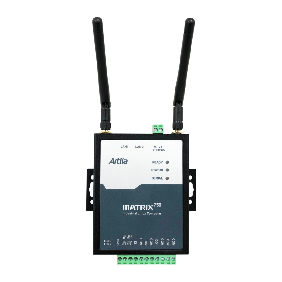
Matrix-750 Hardware Guide 2. Layout Connector & LED Indicator Power Input Hole Hole (Reserved (Reserved for Antenna) for Antenna) Ready LED Console LED / User Define Serial Port LED SIM socket (internal) SD Card Slot (internal) Digital Digital Input Output... -
Page 10: Dimension
Matrix-750 Hardware Guide Dimension Unit: mm 111.0mm 89.0mm ARTILA... -
Page 11: Pin Assignment And Definitions
Matrix-750 Hardware Guide 3. Pin Assignment and Definitions LED Indicators The LED provides the Matrix-750 operation information. The LED status is described as follow: Ready LED LED / User Define Serial Port LED “Ready” (Ready LED indicator): Ready LED keeps ON when system is ready for operating. -
Page 12: Serial Port
Termination Resistor Enabled 1 2 3 Set Serial Port to RS232 port (JP3) The Serial Port on Matrix-750, default is RS-485 at JP3 (setting Pin 3 and Pin4) To Enable RS-232 port, setting JP3 at Pin 1 and Pin 2 ARTILA... -
Page 13: Power Connector
Matrix-750 Hardware Guide Power Connector Connecting +9 ~ +48VDC power line to the Power in terminal block. Power Input Ethernet LAN Port (LAN1 & LAN2) LAN2 LAN1 The Ethernet Port use RJ45 connector. Pin-Assignment as below: Signal ETx + ETx -... -
Page 14: Serial Console Port (Jp2)
Matrix-750 Hardware Guide Serial Console Port (JP2) There is a 4-pin wafer box header (JP2) inside the Matrix-750 features as serial console port that used for locally accessing Matrix-750 system via console port. Console Port Pin assignment is: RX, TX, +3.3V, GND. -
Page 15: Digital Input
Matrix-750 Hardware Guide Digital Input Two channel Digital Input are equipped with 5000Vrms photocoupler isolation which share the same common ground. The specification of the isolated input channels is: Logical High: 5~24Vdc Logical Low: 0~1.5Vdc Input resistance: 1.8KOhms@0.32W Response time: 20µs... -
Page 16: Minipcie Slot
Matrix-750 Hardware Guide miniPCIe Slot The Matrix-750 comes with a miniPCIe (mPCIe) slot and dual holes for antenna reserved for communication/networking functionality. Reserved for Reserved for Antenna Antenna mPCIe slot 3.10 SIM card Socket There is a micro-SIM card socket inside. -
Page 17: Sd Card Socket
Matrix-750 Hardware Guide 3.11 SD card Socket There is a micro-SD card socket inside as data storage. After removed top cover, it can be accessed the SD card. Micro-SD card socket ARTILA...
Need help?
Do you have a question about the Matrix-750 and is the answer not in the manual?
Questions and answers