
Related Manuals for Artila Matrix-310


Summary of Contents for Artila Matrix-310
- Page 1 Matrix-310 Programmable Industrial IoT Gateway Hardware Guide Version: 1.0 2023 January Copyright © Artila Electronics Co., Ltd. All Rights Reserved.
- Page 2 Matrix-310 Hardware Guide Trademarks The Artila logo is a registered trademark of Artila Inc. All other trademarks or registered marks in this manual belong to their respective manufacturers. Disclaimer Information in this document is subject to change without notice and does not represent a commitment on the part of Artila.
- Page 3 Matrix-310 Hardware Guide Document Amendment History Revision Date Remark V 1.0 2023 Jan. Initial ARTILA...
-
Page 4: Table Of Contents
Matrix-310 Hardware Guide Table of Contents Introduction ....................5 Features ....................5 Specifications (Hardware)................ 6 Specifications (Software) ................. 8 Packing List ..................... 8 Optional Accessory.................. 8 Layout ......................9 Connector & LED Indicator ..............9 Mounting ....................9 Dimension ....................10 Pin Assignment and Definitions .............. -
Page 5: Introduction
Matrix-310 from Artila provides multi-communication via an Arduino-based, C/C++ programmable industrial IoT gateway. With the integrated ESP32 Xtensa Dual-Core 32-bit LX6 Microprocessor, Artila’s IoT gateway provides up to 240 MHz of frequency, as well as Wi-Fi (802.11b/g/n, 2.4GHz single band) and dual-mode Bluetooth. -
Page 6: Specifications (Hardware)
Matrix-310 Hardware Guide 1.2 Specifications (Hardware) SOC (ESP32-WROOM-32U) ® • MCU: ESP32-D0WD-V3, Xtensa dual-core 32-bit LX6 microprocessor • Frequency: Up to 240MHz • SDRAM: 520KB for data and instructions • Flash: 448KB for booting and core functions • Wi-Fi (ESP32): IEEE 802.11b/g/n, 2.4GHz single band... - Page 7 Matrix-310 Hardware Guide Digital Input • 2 x Digital Input Channels • Isolation Protection: 5000Vrms (Photo Coupler) • Logical High: 5~24VDC • Logical Low: 0~1.5VDC Power Requirement • Input Voltage: +9~+40VDC • Connector: Terminal block • Typical Power Consumption: 12VDC@150mA Console •...
-
Page 8: Specifications (Software)
Matrix-310 Hardware Guide 1.3 Specifications (Software) Easy to Use C/C++ Platform (Arduino ESP32) • Matrix-310 is C/C++ programmable, Arduino (ESP32) compatible industrial IoT platform • Installed Arduino core (ESP32) through board manager of Arduino IDE Free Application Development Tools ®... -
Page 9: Layout
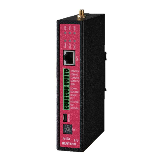
Matrix-310 Hardware Guide 2. Layout 2.1 Connector & LED Indicator 2.2 Mounting ARTILA... -
Page 10: Dimension
Matrix-310 Hardware Guide 2.3 Dimension Dimensions (W x H x D): 30 x 140 x 95mm (1.18 x 5.51 x 3.74in) Unit: mm ARTILA... -
Page 11: Pin Assignment And Definitions
3.1 Power Connector Connecting +9 ~ +40VDC power line to the Power in terminal block. 3.2 LED Indicators The LED provides the Matrix-310 operation information. The LED status is described as follow: “PWR” (Power LED indicator): PWR LED turns on (green color) after 3.3Vdc power activity ... -
Page 12: Ethernet Lan Port
Matrix-310 Hardware Guide 3.3 Ethernet LAN Port There is a 10/100Mbps Ethernet by RJ45 connectors. It is designed via SPI interface (Mode 0 & mode 3) connected to MCU (ESP32) The Ethernet Port use RJ45 connector. Pin-Assignment as below: Signal... -
Page 13: Serial Port
The Matrix-310 provides on-board 120Ohm termination resistor for each RS-485 port. To enable the termination resistor, please remove the upper cover of the Matrix-310, and the adjust the associated jumper to short as below: Termination Resistor Disabled (default) 1 2 3... -
Page 14: Relay Out
Matrix-310 Hardware Guide 3.6 Relay Out There is one Digital Output Channels (Signal Relay). • Contact Rating: 125VAC@0.5A / 30VDC@1.0A • Max. switching Voltage: 125VAC/60VDC • Max. switching Current: 2A • Signals: NC, NO, COM • 1 Form C configuration... -
Page 15: Digital Input
Matrix-310 Hardware Guide 3.7 Digital Input There are two Digital Input channels The specification of the isolated input channels is: Logical High: 5~24Vdc Logical Low: 0~1.5Vdc Isolation resistance: 10 Ohms@500VDC Response time: 20µs (Max.) Isolation: 5000Vrms (Photo Coupler) DI 1~2 DIx: Isolated digital input channels. -
Page 16: Id Setting
Matrix-310 Hardware Guide 3.8 ID Setting Matrix-310 equips an 8-position rotary switch for Device ID setting or Application mode selection. To program/define 8-positions by following the table listed below: (H: High, L: Low) 8 positions (0~7) ESP32 Pin06 (GPI34) Pin11 (GPIO26) -
Page 17: Reset Button
Matrix-310 Hardware Guide 3.9 Reset Button Press this Reset Button (inside the cabinet) to restart the system. Reset Button 3.10 SD card Socket There is a micro-SD card socket inside as data storage. After removed top cover, it can access the SD card.
Need help?
Do you have a question about the Matrix-310 and is the answer not in the manual?
Questions and answers