Advertisement
SAFETY
PLEASE EXAMINE THE PACKING BOX AND EQUIPMENT FOR DAMAGE IMMEDIATELY
When this equipment is shipped, the title passes to the purchaser upon receipt by the carrier. Consequently, claims for material damaged in shipment must be filed by the purchaser against the transportation company when the shipment is received.
SAFETY DEPENDS ON YOU
YESWELDER arc welding and cutting equipment are designed and built with safety. However, your overall safety can be in creased by proper installation and thoughtful operation on your part. DO NOT INSTALL, OPERATE OR REPAIR THIS EQUIPMENT WITHOUT READING THIS MANUAL AND THE SAFETY PRECAUTIONS CONTAINED THROUGHOUT. And most importantly, think before you act and be careful.

This statement appears where the information must be followed precisely to avoid serious personal injury Or loss of life

This statement appears where the information must be followed to avoid minor personal injury or damage to this equipment.
KEEP YOUR HEAD OUT OF THE FUMES

DON'T get too close to the arc. Use corrective lenses if necessary to stay a reasonable distance from the arc.
READ and Obey the Safety Data Sheet (SDS) and the warning label on all welding materials containers.
USE ENOUGH VENTILATION or exhaust at the arc, or both, to keep the fumes and gases from your breathing zone and the general area.
IN A LARGE ROOM OR OUTDOORS, natural ventilation may be adequate if you keep your head Out Of the fumes (See below).
USE NATURAL DRAFTS or fans to keep the fumes away from your face.
If you develop unusual symptoms, see your supervisor. Perhaps the welding atmosphere and ventilation system should be checked
WEAR CORRECT EYE, EAR & BODY PROTECTION

PROTECT your eyes and face with welding helmet properly fitted and with proper grade of filter plate (See ANSI Z49 1).
PROTECT your body from welding spatter and arc flash with protective clothing including woolen clothing, flame-proof apron and gloves, leather leggings, and high boots.
PROTECT others from spatter, flash, and glare with protective screens or barriers.
IN SOME AREAS, protection from noise may be appropriate.
BE SURE protective equipment is in good condition. Also, wear safety glasses in work area AT ALL TIMES.

SPECIAL SITUATIONS
DO NOT WELD OR CUT containers or materials which previously had been in contact with hazardous substances unless they are properly cleaned.
DO NOT WELD OR CUT painted or plated parts unless special precautions with ventilation have been taken. They can release highly toxic fumes or gases.
Additional precautionary measures:

PROTECT compressed gas cylinders from excessive heat, mechanical shocks, and arcs; fasten cylinders so they cannot fall.
BE SURE cylinders are never grounded or part of an electrical circuit.
REMOVE all potential fire hazards from welding area.
ALWAYS HAVE FIRE FIGHTING EQUIPMENT READY FOR IMMEDIATE USE AND KNOW HOW TO USE IT.
CALIFORNIA PROPOSITION 65 WARNINGS
Breathing diesel engine exhaust exposes you to chemicals known to the State of California to cause cancer and birth defects, or other reproductive harm.
- Always start and operate the engine in a well-ventilated area.
- If in an exposed area, vent the exhaust to the outside.
- Do not modify or tamper with the exhaust system.
- Do not idle the engine except as necessary.
For more information go to www.P65warnings.ca.gov/diesel
This product, when used for welding or cutting, produces fumes or gases which contain chemicals known to the State of California to cause birth defects and, in some cases, cancer. (California Health & Safety Code §25249.5 et seq.)
Cancer and Reproductive Harm
www.P65warnings.ca.gov
ARC WELDING CAN BE HAZARDOUS. PROTECT YOURSELF AND OTHERS FROM POSSIBLE SERIOUS INJURY OR DEATH. KEEP CHILDREN AWAY.
PACEMAKER WEARERS SHOULD CONSULT WITH THEIR DOCTOR BEFORE OPERATING.
Read and understand the following safety highlights. For additional safety information, it is strongly recommended you download free PDF of Standard ANSI Z49.1 from the American Welding Society
https://www.aws.org/library/doclib/AWS-Z49-2021.pdf
BE SURE THAT ALL INSTALLATION, OPERATION, MAINTENANCE AND REPAIR PROCEDURES ARE PERFORMED ONLY BY QUALIFIED INDIVIDUALS.
 FOR ENGINE POWERED EQUIPMENT.
- Turn the engine off before troubleshoot ing and maintenance work unless the maintenance work requires it to be running.
- Operate engines in open, well-ventilated areas or vent the engine exhaust fumes outdoors.
![]()
- Do not add the fuel near an open flame welding arc or when the engine is running. Stop the engine and allow it to cool before refueling to prevent spilled fuel from vaporizing on contact with hot engine parts and igniting. Do not spill fuel when filling tank. If fuel is spilled, wipe it up and do not start engine until fumes have been eliminated.
![]()
- Keep all equipment safety guards, covers and devices in position and in good repair. Keep hands, hair, clothing and tools away from V-belts, gears, fans and all other moving parts when starting, operating or repairing equipment.
![]()
- In some cases it may be necessary to remove safety guards to perform required maintenance. Remove guards only when necessary and replace them when the maintenance requiring their removal is complete. Always use the greatest care when working near moving parts.
- Do not put your hands near the engine fan. Do not attempt to override the governor or idler by pushing on the throttle control rods while the engine is running.
- To prevent accidentally starting gasoline engines while turning the engine or welding generator during maintenance work, disconnect the spark plug wires, distributor cap or magneto wire as appropriate.
- To avoid scalding, do not remove the radiator pressure cap when the engine is hot.
![]()


ELECTRIC AND MAGNETIC FIELDS MAY BE DANGEROUS

- Electric current flowing through any conductor causes Iocalized Electric and Magnetic Fields (EMF). Welding cur rent creates EMF fields around welding cables and welding machines.
- EMF fields may interfere with some pacemakers, and welders having a pacemaker should consult their physician before welding.
- Exposure to EMF fields in welding may have other health effects which are now not known.
- All welders should use the following procedures in order to minimize exposure to EMF fields from the welding circuit:
- Route the electrode and work cables together - secure them with tape when possible.
- Never coil the electrode lead around your body.
- Do not place your body between the electrode and work cables. If the electrode cable is on your right side, the work cable should also be on your right side.
- Connect the work cable to the workpiece as close as possible to the area being welded.
- Do not work next to welding power source.
ELECTRIC SHOCK CAN KILL.

- The electrode and work (or ground) circuits are electrically "hot" when the welder is on. Do not touch these "hot" parts with your bare skin or wet clothing.
Wear dry, hole-free gloves to insulate hands. - Insulate yourself from work and ground using dry insulation. Make certain the insulation is large enough to cover your full area of physical contact with work and ground.
In addition to the normal safety precautions, if welding must be performed under electrically hazardous conditions (in damp locations or while wearing wet clothing; on metal structures such as floors, gratings or scaffolds; when in cramped positions such as sitting, kneeling or lying, if there is a high risk of unavoidable or accidental contact with the workpiece or ground) use the following equipment:- Semiautomatic DC Constant Voltage (Wire) Welder.
- DC Manual (Stick) Welder.
- AC Welder with Reduced Voltage Control.
- In semiautomatic or automatic wire welding, the electrode, electrode reel, welding head, nozzle or semiautomatic welding gun are also electrically "hot".
- Always be sure the work cable makes a good electrical connection with the metal being welded. The connection should be as close as possible to the area being welded.
- Ground the work or metal to be welded to a good electrical (earth) ground.
- Maintain the electrode stinger, work clamp, welding cable and welding machine in good, safe operating condition. Replace damaged insulation.
- Never dip the electrode in water for cooling.
- Never simultaneously touch electrically "hot" parts of electrode stingers connected to two welders because voltage between the two can be the total of the open circuit voltage of both welders.
- When working above floor level, use a safety belt to protect yourself from a fall should you get a shock.
ARC RAYS CAN BURN.

- Use a shield with the proper filter and cover plates to protect your eyes from sparks and the rays of the arc when welding or observing open arc welding. Welding shield and filter lens should conform to ANSI Z87. I standards.
- Use suitable clothing made from durable flame-resistant material to protect your skin and that of your helpers from the arc rays.
- Protect other nearby personnel with suitable, nonflammable screening and/or warn them not to watch the arc nor expose themselves to the arc rays or to hot spatter or metal.
FUMES AND GASES CAN BE DANGEROUS.

- Welding may produce fumes and gases hazardous to health. Avoid breathing these fumes and gases. When welding, keep your head out of the fume. Use enough ventilation and/or exhaust at the arc to keep fumes and gases away from the breathing zone.When welding hardfacing (see instructions on container or SDS) or on lead or cadmium plated steel and other metals or coatings which produce highly toxic fumes, keep exposure as low as possible and within applicable OSHA PEL and ACGIH TLV limits using local exhaust or mechanical ventilation unless exposure assessments indicate otherwise. In confined spaces or in some circumstances, outdoors, a respirator may also be required. Additional precautions are also required when welding on galvanized steel.
- The operation of welding fume control equipment is affected by various factors including proper use and positioning of the equipment, maintenance of the equipment and the specific welding procedure and application involved. Worker exposure level should be checked upon installation and periodically thereafter to be certain it is within applicable OSHA PEL and ACGIH TLV limits.
- Do not weld in locations near chlorinated hydrocarbon vapors coming from degreasing, cleaning or spraying operations. The heat and rays of the arc can react with solvent vapors to form phosgene, a highly toxic gas, and other irritating products.
- Shielding gases used for arc welding can displace air and cause injury or death. Always use enough ventilation, especially in confined areas, to insure breathing air is safe.
- Read and understand the manufacturer's instructions for this equipment and the consumables to be used, including the Safety Data Sheet (SDS) and follow your employer's safety practices SDS forms are available from your welding distributor or from the manufacturer.
WELDING AND CUTTING SPARKS CAN CAUSE FIRE OR EXPLOSION.

- Remove fire hazards from the welding area. If this is not possible, cover them to prevent the welding sparks from starting a fire. Remember that welding sparks and hot materials from welding can easily go through small cracks and openings to adjacent areas. Avoid welding near hydraulic lines. Have a fire extinguisher readily available.
- Where compressed gases are to be used at the job site, special precautions should be used to prevent hazardous situations. Refer to "Safety in Welding and Cutting" (ANSI Standard Z49.1) and the operating information for the equipment being used.
- When not welding, make certain no part of the electrode circuit is touching the work or ground. Accidental contact can cause overheating and create a fire hazard.
- Do not heat, cut or weld tanks, drums or containers until the proper steps have been taken to insure that such procedures will not cause flammable or toxic vapors from substances inside. They can cause an explosion even though they have been "cleaned". For information, purchase "Recommended Safe Practices for the Preparation for Welding and Cutting of Containers and Piping That Have Held Hazardous Substances", AWS F4.1 from the American Weld ing Society (see address above).
- Vent hollow castings or containers before heating, cutting or welding. They may explode.
- Sparks and spatter are thrown from the welding arc. Wear oil free protective garments such as leather gloves, heavy shirt, cuffless trousers, high shoes and a cap over your hair. Wear ear plugs when welding out of position or in confined places. Always wear safety glasses with side shields when in a welding area.
- Connect the work cable to the work as close to the welding area as practical. Work cables connected to the building framework or other locations away from the welding area increase the possibility of the welding current passing through lifting chains, crane cables or other alternate circuits. This can create fire hazards or overheat lifting chains or cables until they fail.
- Read and follow NFPA 51B "Standard for Fire Prevention During Welding, Cutting and Other Hot Work", available from NFPA, 1 Batterymarch Park, PO box 9101,Quincy, MA 022690-9101.
- Do not use a welding power source for pipe thawing.
CYLINDER MAY EXPLODE IF DAMAGED.

- Use only compressed gas cylinders containing the correct shielding gas for the process used and properly operating regulators designed for the gas and pressure used. All hoses, fittings, etc. should be suitable for the application and maintained in good condition.
- Always keep cylinders in an upright position securely chained to an undercarriage or fixed support.
- Cylinders should be located:
- Away from areas where they may be struck or subjected to physical damage.
- A safe distance from arc welding or cutting operations and any other source of heat, sparks, or flame.
- Never allow the electrode, electrode stringer or any other electrically "hot" parts to touch a cylinder.
- Keep your head and face away from the cylinder valve outlet when opening the cylinder valve.
- Valve protection caps should always be in place and hand tight except when the cylinder is in use or connected for use.
- Read and follow the instructions on compressed gas cylinders, associated equipment, and CGA publication P-l, "Precautions for Safe Handling of Compressed Gases in Cylinders," available from the Compressed Gas Association, 14501 George Carter way Chantilly, VA 20151.
FOR ELECTRICALLY POWERED EQUIPMENT.

- Turn off the power using the disconnect switch at the fuse box before working on the equipment.
- Install equipment in accordance with the U.S. National Electrical Code, all local codes and the manufacturer's recommendations
- Ground the equipment following the U.S. National Electrical Code and the manufacturer's recommendations.
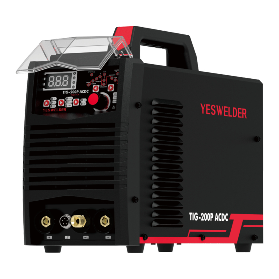
PRODUCT OVERVIEW
The TIG AC/DC series inverter AC/DC pulse argon arc welding machine uses foreign high-quality high-power IGBT as the main switching component for frequency conversion technology, and adopts high-frequency transformers, fast recovery rectifiers, and other high-frequency devices; This machine adopts passive power factor correction, with high power factor, excellent welding process characteristics, dynamic response characteristics, and precise current control; It has ideal static characteristics and good dynamic characteristics, with multiple protection functions such as phase loss, over voltage, under voltage, over current, overheating, etc.
This machine is a high-end mufti-function digital welding machine, which can realize manual arc welding, DC constant current argon arc welding, DC pulse argon arc welding, AC constant current argon arc welding, AC pulse argon arc welding, and is used for welding carbon steel, copper, titanium, aluminum, aluminum magnesium alloys and other materials. Widely used in welding production in various industries such as machinery, automobiles, motorcycles, shipbuilding, metallurgy, mining, construction, bridges, pipe lines, boilers, pressure vessels, etc.
FUNCTION OVERVIEW
This series of welding machines has the following main characteristics:
- IGBT high-frequency hard switch, high efficiency, small size, and light weight;
- This machine has pulse function;
- Pulse argon arc welding is equipped with peak, base, frequency, and duty cycle adjustments, and frequency adjustment range to meet the welding needs of materials with different thicknesses;
- Argon arc welding has two-step, four-step, and repetitive functions, which can be selected according to different process requirements;
- This machine has a constant current characteristic welding machine, which adopts PW M modulation technology and has good constant current characteristics, achieving stable control of welding current, Effectively avoiding welding current changes caused by unskilled welders or fluctuations in grid voltage;
- This machine has functions of early air supply and delayed air cutoff, and the time is adjustable;
- Argon arc welding is equipped with current rise and current drop functions, and the time is adjustable to avoid current impact during arc starting and arc pits formed during welding completion;
- When used for argon arc welding, it has a high-frequency arc striking function, and the success rate of one arc striking reaches 100%;
- Wide adjustment range of welding current, high success rate of low current arc starting, and the minimum arc starting current can be as low as 5A;
- When using AC argon arc welding, the required depth, width, and number of ripples of the weld seam can be obtained by adjusting the pulse current, pulse frequency, duty cycle, AC current, AC frequency, cleaning width, and AC bias ratio, extending the life of the tungsten electrode, especially suitable for automatic welding and robotic welding.
PERFORMANCE CHARACTERISTICS
Advanced IGBT inverter technology
- Inverting frequency of 43 KHz greatly reduces the volume and weight of the welder.
- Great reduction in magnetic and resistance loss obviously enhances the welding efficiency and energy saving effect.
- Working frequency is beyond audio range, which almost eliminates noise pollution.
Leading control mode
- Advanced control technology meets various welding applications and greatly improves the welding performance.
- It can be widely used in acid electrode welding.
- Easy arc starting, less spatter, stable current and good shaping.
Nice shape and structure design
- Front and rear panels in shape of streamline make the whole shape nicer.
- Front and rear panels made of high-intensity plastics can effectively ensure the machine to efficiently work in severe conditions.
- Excellent insulating property.
TECHNICAL PARAMETERS
| Model | TIG-200P ACDC | ||
| Supply voltage (VAC) | 220V/110V | ||
| Input frequency (Hz) | 50/60 | ||
| Rated input peak current (A) | 31.5 | ||
| Power capacity (KVA) | 5.3 | ||
| Rated output current (A) | STICK | 110V: 10~140 / 220V: 10~180 | |
| TIG | 110V: 10~160 / 220V: 10~200 | ||
| No load voltage | 64 | ||
| Pre-Gas time(s) | 0~5 | ||
| Slope-up time(s) | 0~5 | ||
| Initial current (A) | 10~200 | ||
| AC output frequency (Hz) | 40~150 | ||
| Balance (%) | 10~90 | ||
| Slope-down time(s) | 0~5 | ||
| Post-Gas time(s) | 0.1~25 | ||
| Background current (A) | 10~200 | ||
| Pulse frequency (Hz) | 0.2~25 | ||
| Remote control | YES | ||
| Arc start | HF Start | ||
| Efficiency (%) | 85 | ||
| Power factor | 0.73 | ||
| Insulation grade | F | ||
| Enclosure protection class | IP21 | ||
WELDING SOURCE DESCRIPTION
General description

- Operating panel: To set the parameters.
- "+" output terminal
- "-" output terminal
- Control terminal: To connect the signal wire of the TIG torch trigger.
- Gas terminal: To connect the gas hose tie-in of the TIG torch.
- Handle
- Power switch: Power ON/OFF switch.
- Gas inlet: For shield gas input.
- Power input: Power input cable.
- Cooling fan
Display

- Display screen
- Welding parameter adjusting key
- Operation mode selecting key
- DC/AC selecting key
- Indicator for 2T
- Indicator for 4T
- Indicator for spot welding
- Indicator for HF TIG
- Indicator for pulsed TIG
- Indicator for STICK
- Indicator for DC
- Indicator for AC
- Indicator for pre-gas
- Indicator for initial current
- Indicator for up-slope
- Indicator for welding current
- Indicator for AC frequency
- Indicator for base current
- Indicator for AC balance
- Indicator for down-slope
- Indicator for pilot arc current
- Indicator for post gas
- Indicator for pulse frequency/DC balance
- Indicator for spot time
- Welding parameter adjusting knob
- Indicator for remote/foot pedal
- Indicator for work mode
- Indicator for overheat alarm
Parameter auto-saving
The parameters having been adjusted will be auto-saved in thee parameter group currently used (no auto-saving will be done in the case that no operation is done after parameters are adjusted and the machine was turned off in 5s' time). When the machine is turned on next time, the parameters in this parameter group are just the parameters used last time. When the welding mode and operation mode are re-selected, auto-saving will be done in 10s. No special save key and manual saving operation is available for this machine.
Protection function
| A-1 | When the overcurrent indicator illuminates and the digital meter displays "A-1", it indicates that overcurrent occurs. Restart the machine, and welding can be continued. |
| XX C | When the overheating indicator illuminates and the digital meter displays the temperature, it indicates that welding is forced to stop because the main circuit of the machine gets overheated. In this condition, it is unnecessary to turn off the machine, but just wait a few minutes, and then welding can be continued. |
| A-0 | When the digital meter displays: "A-0", it indicates that the current sensor is malfunctioning and there might be a problem with machine components. |
Foot control option (customized)
This machine can identify the foot control automatically. That is to say, the machine will enter into foot control mode automatically after the aviation plug of the foot control is connected to the welding machine and the machine is powered on again. In foot pedal con trol mode, the maximum current is the preset current and the minimum current is 10A.
Voltage indicator (customized)
When this indicator illuminates, it indicates that there is voltage output at the output terminal of the welding machine. When TIG is selected as the welding mode, there will be voltage output only when the torch trigger is pressed continuously and after arc is ignited successfully. When STICK is selected as the welding mode, there will be voltage output whether arc is ignited or not.
INSTALLATION AND OPERATION
Note:
- Please install the machine strictly according to the following steps.
- Turn off the power supply switch before any electric connection operation.
- The housing protection grade of this machine is IP21S, so do not use it in rain.
- Connect the power input terminal (AC230V INPUT) on the back panel of the machine to provisions of the Voltage and with a power cord of appropriate specification throng a fuse with a capacity of 40A or more.
Locate the welding source near the socket, and keep it well ventilated. To ensure good dissipation, the space around the welding source should not be less than 250mm.
Please protect the circuit with delay fuse of corresponding specifications to ensure normal work.
Grounding requirements:
In order to ensure normal work and personal safety and reduce the EMI, the welding source should be grounded reliably.
Installation method
TIG

- Connect the TIG torch correctly according to Fig. 9-1. Connect the connector of the TIG torch to the quick socket on the machine panel, and tighten it clockwise.
- Connect the aviation plug on the TIG torch to the corresponding socket on the machine panel, and tighten it clockwise.
- Insert the quick plug on the earth cable into the "+" quick socket on the machine panel, and tighten it clockwise. Clamp the workpiece with the work clamp at the other end of the earth cable.
- Tightly connect the gas hose to the gas inlet on the back panel of the machine. The gas path should include the cylinder, gas regulator and gas hose. The joint with the hose should be tightened with a hoop to prevent gas leakage and air mixing. Otherwise, weld bead cannot be well protected.
- The enclosure of the machine must be grounded reliably.
STICK

- Insert the cable plug with electrode holder into the "+" socket on the front panel of the welding machine, and tighten it clockwise.
- Insert the cable plug with work clamp into the "-" socket on the front panel of the welding machine, and tighten it clockwise.
- Ground connection is needed for safety purpose.
The connection as mentioned above in 4) and 5) is DCEP connection. Operator can choose DCEN connection according to workpiece and electrode application requirement. Generally, DCEP connection is recommended for basic electrode, while there is no special requirement for acid electrode.
Operation method
STICK
Pay attention to the connection polarity Generally, DCEP and DCEN are available in DC STICK.
DCEP: Connect the electrode holder to "+" output terminal, and the work clamp to "-" output terminal.
DCEN: Connect the electrode holder to "-" output terminal, and the work clamp to "+" output terminal.
Operators may choose connection mode according to workpiece and electrode application requirement. Phenomena such as unstable arc, excessive spatter, and electrode sticking will occur when improper connection mode is selected. Change the polarity by exchanging the quick connectors to solve the problem.
- Anti-sticking function is available for this machine.
 | Select STICK mode by pressing the welding parameter adjusting key, and STICK can be carries out. There is voltage output at both output terminals. |
 | At this time, the voltage indicator illuminates, and welding can be carried out. (customized) |
 | Select welding current setting function by pressing the welding parameter adjusting key, and welding current in STICK can be set. Besides, welding current setting can be carried out during welding. |
HF TIG
 | Select HF TIG mode by pressing the welding mode selecting key, and select 2T/4T/SPOT WELDING mode by pressing the operation mode selecting key. |
 | Select pre-flow time setting function by pressing the welding parameter adjusting key, and set the pre-flow time. |
 | Select initial current setting function by pressing the welding parameter adjusting key, and set the initial current. |
 | Select upslope time setting function by pressing the welding parameter adjusting key, and set the upslope time. |
| Select welding current setting function by pressing the welding parameter adjusting key, and set the welding current. |
 | Select downslope time setting function by pressing the welding parameter adjusting key, and set the downslope time. |
 | Select pilot arc current setting function by pressing the welding parameter adjusting key, and set the pilot arc current. |
 | Select post-flow time setting function by pressing the welding parameter adjusting key, and set the post flow time. |
- After the parameters are set appropriately, open the gas valve of the cylinder, and adjust the gas regulator to the desired value.
- Press the torch trigger, the solenoid valve works. There is gas output firstly, and then HF output.
- Keep the torch 2~4mm away from the workpiece, and then press the torch trigger. After arc is ignited, the HF discharge rustling disappears, the current rises up to the preset value, and welding can be carried out. After releasing the torch trigger, the current begin to decrease automatically to the pilot arc value. Then, arc stops with gas keeping flowing for the post-flow time, and welding ends.
Pulsed TIG
| Select pulsed TIG mode by pressing the welding mode selecting key, and select 2T/4T/SPOT WELDING mode by pressing the operation mode selecting key. |
| Select pre-flow time setting function by pressing the welding parameter adjusting key, and set the pre-flow time. |
| Select initial current setting function by pressing the welding parameter adjusting key, and set the initial current. |
| Select upslope time setting function by pressing the welding parameter adjusting key, and set the upslope time. |
| Select peak welding current setting function by pressing the welding parameter adjust ing key, and set the peak welding current. |
 | Select base current setting function by pressing the welding parameter adjusting key, and set the base current. |
| Select downslope time setting function by pressing the welding parameter adjusting key, and set the downslope time. |
| Select pilot arc current setting function by pressing the welding parameter adjusting key, and set the pilot arc current. |
| Select post-flow time setting function by pressing the welding parameter adjusting key, and set the post-flow time. |
- After the parameters are set appropriately, open the gas valve of the cylinder, and adjust the gas regulator to the desired value.
- Press the torch trigger, the solenoid valve works. There is gas output firstly, and then HF output.
- Keep the torch 2~4mm away from the workpiece, and then press the torch trigger. After arc is ignited, the HF discharge rustling disappears, the current rises up to the preset value, and welding can be carried out. After releasing the torch trigger, the current be gin to decrease automatically to the pilot arc value. Then, arc stops with gas keeping flowing for the post-flow time, and welding ends.
Operation mode function
 | Select 2T mode by pressing the operation mode selecting key. Operation steps in 2T: Press the torch trigger, gas valve opens, and HF arc ignition starts; Keep the torch 2~4mm away from the workpiece to ignite the arc, HF stops, and current rise to the preset value; Release the torch trigger, current decreases to the pilot arc value, and then arc stops; Gas keeps flowing for the post flow time, and welding ends. |
 | Select 4T mode by pressing the operation mode selecting key. Operation steps in 4T: Press the torch trigger, gas valve opens, and HF arc ignition starts; Keep the torch 2~4mm away from the workpiece to ignite the arc, HF stops, and current rise to the preset value; Release the torch trigger, and welding continues under the preset Current; Press the torch trigger again and release it, current begins to decrease to the pilot arc value, and then arc stops; Gas keeps flowing for the post-flow time, and welding ends. |
 | When the foot pedal is connected to the machine, the indicator light will automatically switch to the foot pedal remote mode. |
 | Select spot welding mode by pressing the operation mode selecting key. |
 | Select spot welding time setting function by pressing the welding parameter selecting key, and set the spot welding time. Besides, the spot welding time setting can be carried out during welding. Operation steps in spot welding: Press the torch trigger, gas valve opens, and HF arc ignition starts; Keep the torch 2~4mm away from the workpiece to ignite the arc, HF stops, and current turns to the preset value; Welding begins, and it ends when the spot welding time is up. There is no current upslope and downslope in spot welding mode. |
Parameters for TIG welding on titanium and its alloy (for reference only)
| Plate thickness (mm) | Tungsten electrode (mm) | Welding current (A) | Wire diameter | Gas flow (L/min) | Welding layers | Preheat temperature | Note |
| 1 | 2 | 40~60 | 1.6 | 7~9 | 1 |  | Curling welding |
| 1.5 | 50~80 | 1.6~2.0 | Crimp welding or single face welding | ||||
| 2 | 2~3 | 90~120 | 2~2.0 | 8~12 | Butt welding | ||
| 3 | 3 | 150~180 | 2~3 | V-groove butt welding | |||
| 4 | 4 | 180~200 | 3 | 10~15 | 1~2/1 | ||
| 5 | 180~240 | 3~4 | |||||
| 6 | 5 | 240~280 | 4 | 14~16 | 1~2/1 | ||
| 8 | 260~320 | 4~5 | 2/1 | 100 | |||
| 10 | 280~340 | 3~4/1-2 | 100~150 | ||||
| 12 | 5~6 | 300~360 | 16~20 | 150~200 | |||
| 14 | 340~380 | 5~6 | 180~200 | ||||
| 16 | 6 | 2~3/2~3 | 200~220 | ||||
| 18 | 360~400 | 200~240 | |||||
| 20 | 20~22 | 200~260 | |||||
| 16~20 | 340~380 | 16~22 | 3~4/3~4 | ||||
| 22~25 | 6~7 | 360~400 | 20~22 |
CAUTION
Working Environment
- Welding should be carried out in dry environment with humidity of 90% or less.
- The temperature of the working environment should be between -10ºC and 40ºC.
- Avoid welding in the open air unless sheltered from sunlight and rain. Keep it dry at all times and do not place it on wet ground or in puddles.
- Avoid welding in dusty area or environment with corrosive chemical gas.
- Gas shielded arc welding should be operated in environment without strong airflow.
- Place the machine directly on a secure, level surface. Do not place or operate this machine on a surface with an incline greater than 15º from horizontal. The machine may topple over if this procedure is not followed.
- The machines level of electromagnetic compatibility is Class A. Equipment shall not apply to public low-voltage power supply system power supply of residential environment. Because of conduction and radiation harassment, in these environments are difficult to ensure electromagnetic compatibility.
Safety Tips
Overcurrent/overvoltage/overheating protection circuit is installed in this machine. When the mains voltage, output current or inner temperature exceeds the set standard, the machine will stop automatically. However, excessive use (e.g. too high voltage) of machine will lead to welder damage.
Therefore, please note:
- Ventilation
This welder can create powerful welding current that has strict cooling requirements that cannot be met with natural ventilation. Therefore, the internal fan is very important in enabling the machine to work steadily with effective cooling. The operator should make sure that the louvers be uncovered and unblocked. The minimum distance between the machine and nearby objects should be 30cm. Good ventilation is of critical importance to the normal performance and lifespan of the machine. - Welding operation is forbidden while the machine is overloaded. Remember to observe the max load current at any moment (refer to the corresponding duty cycle). Make sure that the welding current should not exceed the maximum load current. Overload could obviously shorten the machine's lifespan, or even damage the machine.
- Over-voltage is forbidden
Regarding the power supply voltage range of the machine, please refer to "Technical Parameters" table. This machine is of automatic voltage compensation, which enables the maintaining of the voltage range within the given range. In case that the input voltage exceeds the stipulated value, it would possibly damage the components of the machine. - An earth terminal is available for the machine. Connect it with an earth cable to avoid the static and electric shock.
- A sudden halt may occur with the overheating indicator on the front panel on while the machine is of overload status. Under this circumstance, it is unnecessary to restart the machine. Keep the built-in fan working to lower the temperature inside the machine. Welding can be continued after the inner temperature falls into the standard range and the overheating indicator is off.
TROUBLESHOOTING
The following operation requires sufficient professional knowledge on electric aspect and comprehensive safety knowledge. Operators should be holders of valid qualification certificates which can prove their skills and knowledge. Make sure the input cable of the machine is disconnected from the electricity utility before uncovering the welding machine.
Common Malfunction Analysis and Solution
| Malfunction Phenomena | Causes and Solutions | |||||
| Turn on the machine, the power indicator does not illuminate, the fan doesn't work, and no welding output. |
| |||||
| Turn on the machine, the fan works, but the output current is unstable and can't be controlled by potentiometer when welding. |
| |||||
| Turn on the machine, the power indicator illuminates, the fan works, but no welding output. |
| |||||
| The electrode holder becomes very hot. | The rated current of the electrode holder is smaller than its actual working current. Replace it with a bigger rated current. | |||||
| Excessive spatter in STICK welding. | The output polarity connection is incorrect. Exchange the polarity. | |||||
 .
. .
.This product is being improved unceasingly, so differences may appear in parts except for functions and operation. Thanks for understanding.
PACKING, TRANSPORTATION AND STORAGE
Transportation
Equipment should be handled with care in transportation to avoid severe impact. Equipment should be prevented from being affected with damp and caught in the rain in transportation.
Storage
Temperature for storage: -25ºC~+50ºC
Humidity for storage: relative humidity ≤90%
Storage life: 12 months
Place for storage: ventilated indoor place without corrosive gas
WE ALWAYS STAND BEHIND IT
Toll Free (855) 937-4567
Documents / Resources
References
![www.p65warnings.ca.gov]() http://www.p65warnings.ca.gov/diesel
http://www.p65warnings.ca.gov/diesel![www.p65warnings.ca.gov]() http://www.p65warnings.ca.gov
http://www.p65warnings.ca.gov![www.yeswelder.com]() Welder, Plasma Cutter, Welding Helmet, Welding Equipment – YesWelder
Welder, Plasma Cutter, Welding Helmet, Welding Equipment – YesWelder

Download manual
Here you can download full pdf version of manual, it may contain additional safety instructions, warranty information, FCC rules, etc.
Download YESWELDER TIG-200P ACDC - Aluminum TIG Welder Manual
Advertisement


Need help?
Do you have a question about the TIG-200P and is the answer not in the manual?
Questions and answers