Advertisement
SAFETY

CALIFORNIA PROPOSITION 65 WARNINGS
Diesel engine exhaust and some of its constituents are known to the State of California to cause cancer, birth defects, and other reproductive harm.
The Above For Diesel Engines
 FOR ENGINE POWERED EQUIPMENT.
-
- Turn the engine off before troubleshooting and maintenance work unless the maintenance work requires it to be running.
- Operate engines in open, well-ventilated areas or vent the engine exhaust fumes outdoors
![]()
- Do not add the fuel near an open flame welding arc Or when the engine is running. Stop the engine and allow it to cool before refueling to prevent spilled fuel from vaporizing on contact with hot engine parts and igniting DO not spill fuel when filling tank. If fuel is spilled, wipe it up and do not start engine until fumes have been eliminated
![]()
- Keep all equipment safety guards, covers and devices in position and in good repair. Keep hands, hair, cloth ing and tools away from V-belts, gears, fans and all Other moving parts when starting, operating or repairing equipment.
- In some cases it may be necessary to remove safety guards to perform required maintenance. Remove guards Only when necessary and replace them when the maintenance requiring their removal is complete. A1 ways use the greatest care when working near moving parts
- If Do not put your hands near the engine fan. DO not attempt to override the governor or idler by pushing on the throttle control rods while the engine is running.
![]()
- To prevent accidentally starting gasoline engines while turning the engine or welding generator during maintenance work, disconnect the spark plug wires, distributor cap or magneto wire as appropriate


The engine exhaust from this product contains chemicals known to the State of California to cause cancer, birth defects, or other reproductive harm
The Above For Gasoline Engines
-
- To avoid scalding, do not remove the radiator pressure cap when the engine i hot.
![]()
- To avoid scalding, do not remove the radiator pressure cap when the engine i hot.

ELECTRIC AND MAGNETIC FIELDS MAY BE DANGEROUS

-
- Electric current flowing through any conductor causes localized Electric and Magnetic Fields (EMF). Welding current creates EMF fields around welding cables and welding machines
- EMF fields may interfere with some pacemakers, and welders having a pacemaker should consult their physician before welding.
- Exposure to EMF fields in welding may have other health effects which are now not known.
- All welders should use the following procedures in order to minimize exposure to EMF fields from the welding circuit:
- Route the electrode and work cables together - Secure them with tape when possible.
- Never coil the electrode lead around your body.
- Do not place your body between the electrode and workcables. If the electrode cable is on your right side, the work cable should also be on your right side.
- Connect the work cable to the workpiece as close as possible to the area being welded.
- Do not work next to welding power source.
 ELECTRIC SHOCK CAN KILL.

-
- The electrode and work (or ground) circuits are electrically "hot" when the welder is on. Do not touch these "hot" parts with your bare skin or wet clothing. Wear dry, hole-free gloves to insulate hands.
- Insulate yourself from work and ground using dry insulation. Make certain the insulation is large enough to cover your full area of physical contact with work and ground.
In addition to the normal safety precautions, if welding must be performed under electrically hazardous conditions (in damp locations or while wearing wet clothing; on metal structures such as floors, gratings or scaffolds; when in cramped positions such as sitting, kneeling or lying, if there is a high risk of unavoidable or accidental contact with the workpiece or ground) use the following equipment:- Semiautomatic DC Constant Voltage (Wire) Welder.
- DC Manual (Stick) Welder.
- AC Welder with Reduced Voltage Control.
- In semiautomatic or automatic wire welding, the electrode, electrode reel, welding head, nozzle or semiautomatic welding gun are also electrically "hot".
- Always be sure the work cable makes a good electrical connection with the metal being welded. The connection should be as close as possible to the area being welded.
- Ground the work or metal to be welded to a good electrical (earth) ground.
- Maintain the electrode stinger, work clamp, welding cable and welding machine in good, safe operating condition. Replace damaged insulation.
- Never dip the electrode in water for cooling.
- Never simultaneously touch electrically "hot" parts of electrode stingers connected to two welders because voltage between the two can be the total of the open circuit voltage of both welders.
- When working above floor level, use a safety belt to protect yourself from a fall should you get a shock.
- Also see Items 6.c. and 8.
ARC RAYS CAN BURN.

-
- Use a shield with the proper filter and cover plates to protect your eyes from sparks and the rays of the arc when welding or observing open arc welding. Welding shield and filter lens should conform to ANSI Z87. I standards.
- Use suitable clothing made from durable flame-resistant material to protect your skin and that of your helpers from the arc rays.
- Protect other nearby personnel with suitable, nonflammable screening and/or warn them not to watch the arc nor expose themselves to the arc rays or to hot spatter or metal.
FUMES AND GASES CAN BE DANGEROUS.

-
- Welding may produce fumes and gases hazardous to health. Avoid breathing these fumes and gases. When welding, keep your head out of the fume. Use enough ventilation and/or exhaust at the arc to keep fumes and gases away from the breathing zone. When welding hardfacing (see instructions on container or SDS) or on lead or cadmium plated steel and other metals or coatings which produce highly toxic fumes, keep exposure as low as possible and within applicable OSHA PEL and ACGIH TLV limits using local exhaust or mechanical ventilation unless exposure assessments indicate otherwise. In confined spaces or in some circumstances, outdoors, a respirator may also be required. Additional precautions are also required when welding on galvanized steel.
- The operation of welding fume control equipment is affected by various factors including proper use and positioning of the equipment, maintenance of the equipment and the specific welding procedure and application involved. Worker exposure level should be checked upon installation and periodically thereafter to be certain it is within applicable OSHA PEL and ACGIH TLV limits.
- Do not weld in locations near chlorinated hydrocarbon vapors coming from degreasing, cleaning or spraying operations. The heat and rays of the arc can react with solvent vapors to form phosgene, a highly toxic gas, and other irritating products.
- Shielding gases used for arc welding can displace air and cause injury or death. Always use enough ventilation, especially in confined areas, to insure breathing air is safe.
- Read and understand the manufacturer's instructions for this equipment and the consumables to be used, including the Safety Data Sheet (SDS) and follow your employer's safety practices. SDS forms are available from your welding distributor or from the manufacturer.
- Also see item 1.b.
WELDING AND CUTTING SPARKS CAN CAUSE FIRE OR EXPLOSION.

-
- Remove fire hazards from the welding area. If this is not possible, cover them to prevent the welding sparks from starting a fire. Remember that welding sparks and hot materials from welding can easily go through small cracks and openings to adjacent areas. Avoid welding near hydraulic lines. Have a fire extinguisher readily available.
- Where compressed gases are to be used at the job site, special precautions should be used to prevent hazardous situations. Refer to "Safety in Welding and Cutting" (ANSI Standard Z49.1) and the operating information for the equipment being used.
- When not welding, make certain no part of the electrode circuit is touching the work or ground. Accidental contact can cause overheating and create a fire hazard.
- Do not heat, cut or weld tanks, drums or containers until the proper steps have been taken to insure that such procedures will not cause flammable or toxic vapors from substances inside. They can cause an explosion even though they have been "cleaned". For information, purchase "Recommended Safe Practices for the Preparation for Welding and Cutting of Containers and Piping That Have Held Hazardous Substances", AWS F4.1 from the American Welding Society (see address above).
- Vent hollow castings or containers before heating, cutting or welding. They may explode.
- Sparks and spatter are thrown from the welding arc. Wear oil free protective garments such as leather gloves, heavy shirt, cuffless trousers, high shoes and a cap over your hair. Wear ear plugs when welding out of position or in confined places. Always wear safety glasses with side shields when in a welding area.
- Connect the work cable to the work as close to the welding area as practical. Work cables connected to the building framework or other locations away from the welding area increase the possibility of the welding current passing through lifting chains, crane cables or other alternate circuits. This can create fire hazards or overheat lifting chains or cables until they fail.
- Also see item 1.c.
- Read and follow NFPA 51B "Standard for Fire Prevention During Welding, Cutting and Other Hot Work", available from NFPA, 1 Batterymarch Park, PO box 9101, Quincy, MA 022690-9101.
- Do not use a welding power source for pipe thawing.
CYLINDER MAY EXPLODE IF DAMAGED.

-
- Use only compressed gas cylinders containing the correct shielding gas for the process used and properly operating regulators designed for the gas and pressure used. All hoses, fittings, etc. should be suitable for the application and maintained in good condition.
- Always keep cylinders in an upright position securely chained to an undercarriage or fixed support.
- Cylinders should be located:
- way from areas where they may be struck or subjected to physical damage.
- A safe distance from arc welding or cutting operations and any other source of heat, sparks, or flame.
- Never allow the electrode, electrode stinger or any other electrically "hot" parts to touch a cylinder.
- Keep your head and face away from the cylinder valve outlet when opening the cylinder valve.
- Valve protection caps should always be in place and hand tight except when the cylinder is in use or connected for use.
- Read and follow the instructions on compressed gas cylinders, associated equipment, and CGA publication P-l, "Precautions for Safe Handling of Compressed Gases in Cylinders," available from the Compressed Gas Association 1235 Jefferson Davis Highway, Arlington, VA 22202
FOR ELECTRICALLY POWERED EQUIPMENT.

-
- Install equipment in accordance with the U.S. National Electrical Code, all local codes and the manufacturer's recommendations.
- Ground the equipment following the U.S. National Electrical Code and the manufacturer's recommendations.
INSTALLATION SECTION
TECHNICAL SPECIFICATIONS
TECHNICAL SPECIFICATION: YWA-160
| INPUT-SINGLE PHASE ONLY | ||||
| Standard Voltage/Frequency | Input Current | |||
| 220V±10% 50/60Hz | I1 max=29A, I1 eftf=22.4A | |||
| 110V±10% 50/60Hz | I1 max=38A, I1 eff=29.4A | |||
| RATED OUTPUT - DC ONLY | ||||
| Voltage | Mode | Duty Cycle | Current | Volts at Rated Current |
| 220V | SMAW | 60% | 160A | 26.4V |
| 100% | 124A | 25V | ||
| 220V | GTAW | 60% | 160A | 16.4V |
| 100% | 124A | 15V | ||
| 110V | SMAW | 60% | 120A | 24.8V |
| 100% | 93A | 23.7V | ||
| 110V | GTAW | 60% | 120A | 14.8V |
| 100% | 93A | 13.7V | ||
| OUTPUT RANGE | ||||
| Voltage | Mode | Open Circuit Voltage | Welding Current Range | Welding Voltage Range |
| 220V | SMAW | 72V | 20A-160A | 20.8V-26.4V |
| 110V | 20A-120A | 20.8V-24.8V | ||
| 220V | GTAW | 72V | 15A-160A | 10.6v-16.4V |
| 110V | 15A-120A | 10.6V-14.8V | ||
| PHYSICAL DIMENSIONS | ||||
| Machine | Length | Width | Depth | Weight |
| YWA-160 | 15.6in. | 7.7in. | 13in. | Approx. 151bs. |
| TEMPERATURE RANGE | ||||
| Operating Temperature Range | -10ºC-+40ºC (14ºF-104ºF) | |||
| Storage Temperature Range | -25ºC-+55ºC (-13ºF-131ºF) | |||
Read entire installation section before starting installation.
SAFETY PRECAUTIONS

ELECTRIC SHOCK can kill.

- Only qualified personnel should perform this installation.
- Disconnect input power by removing plug from receptacle before working inside YWA-160. Allow machine to sit for 5 minutes minimum to allow the power capacitors to discharge before working inside this equipment.
- Insulate yourself from the work and ground.
- Always wear dry insulating gloves.
- Always connect the YWA-160 to a power supply grounded according to the National Electrical Code and local codes.
SELECT SUITABLE LOCATION
This machine can operate in harsh environments However, it is important that simple preventative measures are followed to assure long life and reliable operation:
- DO not use this machine for pipe thawing
- This machine must be located where there is free circulation of clean air without restrictions for air movement to and from the air vents. Do not cover the machine with pa per, cloth or rags when switched On
- Dirt and dust that can be drawn into the machine should be kept to a minimum
- This machine has a protection rating of IP21S Keep it dry when possible and do not place it on wet ground or in puddles.
- Locate the machine away from radio controlled machinery Normal operation may adversely affect the operation of nearby radio controlled machinery, which may result in injury or equipment damage. Read the section on electro magnetic compatibility in this manual
- Do not operate in areas with an ambient temperature greater than 40ºC
STACKING
The Invertec YWA-160 cannot be stacked.
TILTING
Place the machine directly on a secure, level surface. Do not place or operate this machine on a surface with an incline greater than 150 from horizontal. The machine may topple over if this procedure is not followed.
INPUT CONNECTIONS
ELECTRIC SHOCK can kill.
- Have a qualified electrician install and service this equipment.
- Disconnect input power by removing plug from receptacle before working inside YWA-160. Allow machine to sit for 5 minutes minimum to allow the power capacitors to discharge before working inside this equipment.
- Do not touch electrically live parts
GROUND CONNECTION

A grounding conductor is supplied in the input cord, it is important that the supply receptacle ground is connected.
This installation should be performed by a qualified electrician to ensure correct connections of the leads to the plug spades.
- The electrical system must be made by skilled technicians with the specific professional and technical qualifications and in compliance with the regulations in force in the country where the equipment is installed.
- The welding power source supply cable is provided with a green or yellow/green wire that must ALWAYS be earthed. This green or yellow/green wire must NEVER be used with other voltage conductors.
- Install only plugs that confirm with safety regulations.
INPUT POWER CONNECTION
Check the input voltage, phase, and frequency supplied to this machine before turning it on. The allowable input voltage is indicated in the technical specification section of this manual and on the rating plate of the machine Be sure that the machine is grounded Make sure the power available at the input connection is adequate for normal operation of the machine.
OUTPUT CONNECTIONS
A quick disconnect system using Twist-Mate cable plugs is used for the welding cable connections. Refer to the following sections for more information on connecting the machine for operation of stick welding (MMA) or TIG welding.
ELECTRIC SHOCK can kill.

- Keep the electrode holder and cable insulation in good condition.
- Do not touch electrically live parts or electrode with skin or wet clothing.
- Insulate yourself from work and ground.
- Turn the input line Switch on the YWA-160"0ff" before connecting or disconnecting out-put cables or other equipment.
STICK WELDING
First determine the proper electrode polarity for the electrode to be used. Consult the electrode data for this information Then connect the output cables to the output terminals of the machine for the selected polarity Shown here is the connection method for DC(+) welding (SEE FIGURE A.1) Connect the electrode cable to the (+) terminal and the work clamp to the (-) terminal Insert the connector with the key lining up with the keyway turn clockwise. Do not over tighten For DC(-) welding, switch the cable connections at the ma chine so that the electrode cable is connected to (-) and the work clamp is connected to (+).

TIG WELDING
This machine does not have a built in Gas Solenoid so a one piece gas valve TIG Torch is required. A TIG Torch adapter is also required. Refer to the accessories section in www.yeswelder.com for more information about TIG Torches and required Twistmate adapter. Most TIG welding is done with DC(-) polarity shown here If DC(+) polarity is necessary switch the cable connections at the machine.(SEE FIGURE Connect the torch cable to the (-) terminal of the machine and the work clamp to the (+) terminal. Insert the connector with the key lining up with the keyway and turn clockwise DO not over tighten. Finally, connect the gas hose to the gas regulator on the cylinder of gas to be used.

OPERATION
Read and understand this entire section before operating your machine.
SAFETY INSTRUCTIONS
 | ELECTRIC SHOCK CAN KILL.
|
 | FUMES AND GASES can be dangerous.
|
 | WELDING, CUTTING and GOUGING SPARKS can cause fire or explosion
|
 | ARC RAYS can burn.
|
Only qualified personnel should operate this equipment. Observe all safety information throughout this manual.
GENERAL DESCRIPTION
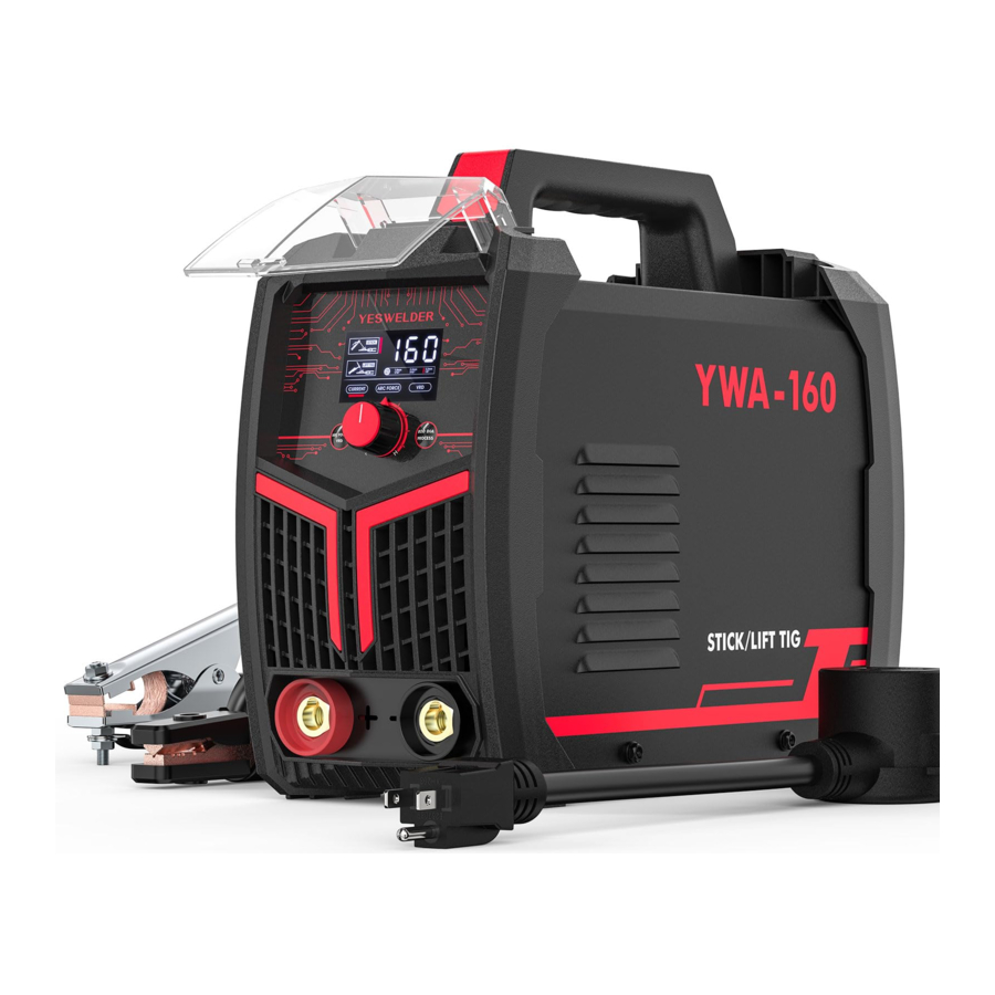
The Y WA-160 is an 160 amp arc welding power source which utilizes single phase input power, to produce constant current Output The welding response of this machine has been optimized for stick (SMAW) and Lift Start TIG (GTAW).
WELDING CAPABILITY
The Invertec YWA-160 is rated at 160 amps, 26.4 volts, at 60% duty cycle on a ten minute basis It is capable of higher duty cycles at lower output currents(l). If the duty cycle is exceeded, a thermal protector will shut off the output until the machine cools. See Technical Specifications in the Installation Section for Other rated outputs.
LIMITATIONS
The YWA-160 is not recommended for pipe thawing
(1) Refer to Technical Specifications in the Installation Section for other ratings.
CONTROLS AND OPERATIONAL FEATURES

- Amperage Display
Displays the current amperage and other settings - Control Knob
Used to set output current and to adjust settings. - ROD DW PROCESS
Press to select MMA, 1.6mm 1/1 6", 2.4mm 3/32", 3.2mm 1/8", If a diameter is selected, the system will automatcally match the adjustable current range to the diameter.
Press and hold (approx. 3 seconds) to choose between MMA, Lift TIG - ARC FORCE/ VRD
Press to select ARC FORCE, VRD. Only functions in MMA Welding
- Positive Output Terminal
Positive output connector for the welding circuit. - Negative Output Terminal
Negative output connector for the welding circuit - Power Switch
It turns ON/OFF the output power to the machine - Input Cable
YESWELDER machines are provided with a plugged input cord, Connect it to the mains. The Stick welding mode also includes the following features:- Hot Start: This is a temporary increase in the initial welding current. This helps ignite the arc quickly and reliable.
ACCESSORIES

- MWA-160 stick Welder
- Work Clamp
- Electrode Holder
- 220V-1 Adapter
MAINTENANCE
SAFETY PRECAUTIONS
ELECTRIC SHOCK can kill.

- Have an electrician install and service this equipment.
- Turn the input power off at the fuse box, disconnect supply lines and allow machine to sit for five minutes minimum to allow the power capacitors to discharge before working inside this equipment.
- Do not touch electrically hot parts
INPUT FILTER CAPACITOR DISCHARGE PROCEDURE
For any maintenance or repair operations it is recommended to contact YESWELDER, support@yeswelder.com or personnel will null and void the manufacturers warranty
The machine has internal capacitors which are charged to a high voltage during power-on conditions. This voltage is dangerous and must be discharged before the machine can be serviced. Discharging is done automatically by the machine each time the power is switched off However, you must allow the machine to sit for at least 5 minutes to allow time for the process to take place
ROUTINE MAINTENANCE
The frequency of the maintenance operations may vary in accordance with the working environment. Any noticeable dam age should be reported immediately
- Check cables and connections integrity. Replace, if necessary
- Clean the power source inside by means of low - pressure compressed air.
- Keep the machine clean. Use a soft dry cloth to clean the external case, especially the airflow inlet / outlet louvers
Do not open this machine and do not introduce anything into its openings. Power supply must be disconnected from the machine before each maintenance and service. After each repair, perform proper tests to ensure safety.

Power supply must be disconnected from the machine before each maintenance and service. Always use gloves in compliance with the safety standards.
TROUBLESHOOTING
HOW TO USE TROUBLESHOOTING GUIDE
This Troubleshooting Guide is provided to help you locate and repair possible machine malfunctions. Simply follow the three step procedure listed below.
- LOCATE PROBLEM (SYMPTOM)
Look under the column labeled "PROBLEM (SYMPTOMS)" This column describes possible symptoms that the machine may exhibit. Find the listing that best describes the symptom that the machine is exhibiting - POSSIBLE CAUSE
The second column labeled "POSSIBLE CAUSE" lists the obvious external possibilities that may contribute to the ma chine symptom - RECOMMENDED COURSE of ACTION
This column provides a course of action for the Possible Cause, generally it states to contact your local Lincoln Authorized Field Service Facility
If you do not understand or are unable to perform the Recommended Course of Action safely, Contact YESWELDER, support@yeswelder.com.
OBSERVE ALL SAFETY GUIDELINES DETAILED THROUGHOUT THIS MANUAL
| PROBLEMS (SYMPTOMS) | POSSIBLE CAUSE | RECOMMENDED COURSE of ACTION |
| PROBLEMS IN STICK WELDING | If all recommended possible areas of misadjustment have been checked and the problem persists, Contact YESWELDER, support@yeswelder.com. | |
Excessive spatter |
| |
Craters |
| |
Inclusions |
| |
Insufficient penetration |
| |
Sticking |
| |
Porosity |
| |
Cracks |
| |
If for any reason you do not understand the test procedures or are unable to perform the tests/repairs safely, Contact YESWELDER, support@yeswelder.com.
OBSERVE ALL SAFETY GUIDELINES DETAILED THROUGHOUT THIS MANUAL
| PROBLEMS (SYMPTOMS) | POSSIBLE CAUSE | RECOMMENDED COURSE of ACTION |
| PROBLEMS IN TIG WELDING | If all recommended possible areas of misadjustment have been checked and the problem persists, Contact YESWELDER, support@yeswelder.com. | |
Oxidation |
| |
Tungsten inclusions |
| |
Porosity |
| |
Hot cracking |
| |
OBSERVE ALL SAFETY GUIDELINES DETAILED THROUGHOUT THIS MANUAL
| PROBLEMS (SYMPTOMS) | POSSIBLE CAUSE | RECOMMENDED COURSE of ACTION |
| ELECTRICAL FAILURES | If all recommended possible areas of misadjustment have been checked and the problem persists, Contact YESWELDER, support@yeswelder.com. | |
| Over-current (Error Code: E1) |
| |
| Overheating (Error Code: E2) |
| |
STICK WELDING ISSUES
| PROBLEM | POSSIBLE CAUSE | COURSE of ACTION |
Poor starting | Poor work clamp connection | Check and secure work connection |
| Stick electrode "blasts Off" when arc is struck. | Current may be set too high for eledrode size | Adjust current. |
| Electrode "stick" in weld puddle | Current may be set too low for electrode Size. | Adjust current. |
| Porosity - small cavities or holes result ing from gas pockets in weld metal | Arc length too long | Reduce arc length |
| Damp electrode | Use dry electrode | |
| Workpiece dirty | Remove all grease, Oil, moisture, rust, paint, coatings, slag, and dirt from work surface before welding | |
| Excessive Spatter - scattering of molten metal particles that cool to solid form near weld bead. | Amperage too high for electrode | Decrease amperage or select larger electrode. |
| Arc length too long or voltage too high. | Reduce arc length or voltage | |
| Incomplete Fusion failure of weld metal to fuse completely with base metal or a preceding weld bead. | Insufficient heat input. | Increase amperage Select larger electrode and increase amperage |
| Improper welding technique | Place stringer bead in proper location at joint during welding | |
| Adjust work angle or widen groove to access bottom during welding | ||
| Momentarily hold arc on groove side walls when using weaving technique | ||
| Keep arc on leading edge of weld puddle | ||
| Workpiece dirty | Remove all grease, oil, moisture, rust, paint, coatings, slag, and dirt from work surface before welding | |
| Lack of Penetration shallow fusion between weld metal and base metal | Improper joint preparation | Material too thick. Joint preparation and design must provide access to bottom of groove |
| Improper weld technique. | Keep arc on leading edge of weld puddle | |
| Insufficient heat input. | Increase amperage Select larger electrode and increase amperage | |
| Burn Through weld metal melting completely through base metal resulting in holes where no metal remains. | Excessive heat input | Reduce travel speed |
| Select lower amperage. Use smaller electrode. | ||
| Increase or maintain steady travel speed |
TIG WELDING ISSUES
| PROBLEM | POSSIBLE CAUSE | COURSE of ACTION |
| Poor starting | Poor work clamp connection | Check and secure work connection. |
| Start current is too low | Increase Start current. | |
| Black area along weld bead | Oily or organic contamination on work | Clean work piece |
| Tungsten electrode may be contaminated | Grind to clean electrode. | |
| Leaks in gas line or torch connection. | Check connection | |
| Gas tank is near empty | Replace the gas tank. | |
| Unstable Arc. | Contaminated base metal | Remove materials like paint, grease, oil, and dirt, including mill scale from base metal |
| Tungsten is contaminated. | Remove 25/64" of contaminated tungsten and re-grind the tungsten | |
| Arc length too long | Lower torch so that the tungsten is Off of the work piece 5/64"-13/64" (2-5mm). | |
| Arc wanders. | Tungsten incorrect or in poor condition | Check that correct type of tungsten is being used. Remove tungsten 3/4" from the weld end and re-sharpen the tungsten |
| Insufficient gas shielding | Check and set the gas flow between 20-30cfh flow rate. | |
| Contaminated gas or leaks in gas line, torch, or connections. | Check gas line & connections | |
| Poorly prepared tungsten. | Grind marks should run lengthwise with tungsten, not circular. Use proper grinding method and wheel. | |
| Contaminated base metal. | Remove contaminating materials like paint, grease, Oil, and dirt, including mill scale from base metal. | |
| Contaminated/lncorrect filler. | Check the filler wire and remove all grease, Oil, or moisture from filler metal. | |
| Lift TIG does not initiate an arc | No gas, incorrect gas flow | Check the gas is connected and cylinder valve open, check hoses, gas valve and torch are not restricted Set the gas flow between 20-30 cfh flow rate. |
| Poor work clamp connection | Check & secure work clamp | |
| Contaninated Tungsten | Grind to clean Tungsten | |
| Loose connection | Check all connectors and tighten | |
| Earth clamp not connected to work | Connect the work clamp directly to the work piece wherever possible | |
| Tungsten burning away quickly | Incorrect Gas/lnadequate gas flow | Check the gas cylinder contains pure Argon gas and is connected and the torch gas valve is open. Set the gas flow between 20-30cfh flow rate |
| Back cap not fitted correctly | Make sure the torch back cap is fitted so that the O-ring is inside the torch body. | |
| Incorrect tungsten being used | Check and change the tungsten type if necessary | |
| Contaminated tungsten | Touching tungsten into the weld pool. | Keep tungsten from contacting weld puddle. Raise the torch so that the tungsten is off of the work piece 1/8-1/4. |
| Touching the filler wire to the tungsten | Keep the filler wire from touching the tungsten during welding, feed the filler wire into the leading edge of the weld pool in front of the tungsten | |
| Tungsten melting into the weld pool. | Check that correct type of tungsten is being used Too much current for the tungsten size so reduce the amps or change to a larger tungsten |
WIRING DIAGRAM
NOTE: This diagram is for reference only It may not be accurate for all machines covered by this manual. The specific diagram for a particular code is pasted inside the machine on one of the enclosure panels. If the diagram is illegible, write to the Service Department for a replacement. Give the equipment code number.

|  |  |  |
|
|
|
READ AND UNDERSTAND THE MANUFACTURER'S INSTRUCTION FOR THIS EQUIPMENT AND THE CONSUMABLES TO BE USED AND FOLLOW YOUR EMPLOYER'S SAFETY PRACTICES.
 |  |  | |
|
|
|
www.yeswelder.com
Toll Free (855) 937-4567
Documents / Resources
References
Download manual
Here you can download full pdf version of manual, it may contain additional safety instructions, warranty information, FCC rules, etc.
Advertisement


Need help?
Do you have a question about the YWA-160 and is the answer not in the manual?
Questions and answers