Advertisement
Quick Links
Read, Understand, Follow and Save These Instr uctions
Read, understand and follow all instructions before installing and using this product. Never allow anyone unfamiliar with the operating instructions to
use this product.
Read, understand and follow all instructions provided by the manufacturer of the product(s) that this product will be installed on.
Installation of this product must conform to the following mounting instructions only.
Save these instructions for use as a reference in the future.
WARNING
Purchaser/owner must ensure that product is
installed according to these instructions. Pur-
chaser/owner must not alter or modify product.
Operator and bystanders should never position
any part of body under any portion of this prod-
uct or the load being supported.
Do not allow children to play on or around this
product or the load being supported.
Never exceed maximum rated capacity. Refer to
stamped markings or decals on product to obtain
Installation Instr uctions
Instructions for Field Installation:
1.
Remove the jack cross shaft. If your jack has non-welded hex bushings, refer to Service
Bulletin F3310 (included). If your jack has welded round journals, refer to Service Bulletin
011926 (included). If you are installing the powered drive on a planetary two speed jack,
refer to Service Bulletin F3376 (included). Refer to steps #1 through #5 for instructions on
removing the cross shaft.
2.
If your date code is before E06 (May 2006), then you will also need to change out the
bevel gear (included) to accommodate the larger dowel pin (included). The date code is
stamped on the outer tube. The letter of the date code corresponds to the month of manufac-
ture (A thru N; A means January) and the numbers correspond to the year (i.e. 06 means
2006). The dowel pin hole in the screw rod will need to be drilled out to 5/16 to accommo-
date the larger dowel pin (enclosed). Please refer to the appropriate Service Bulletin (see
above) for the disassembly procedure.
3.
Replace the jack cross shaft temporarily with the powered drive/shaft. Install the shaft
such that the powered drive is on the non-geared side of the jack with the motor down and
within the profile of the jack (see Fig. 1). For a tandem jack system, the powered drive
should be between the two jacks and installed on the street-side jack. For the tandem two-
speed installation, the grease zerks will no longer be easily accessible. Your option is to drill
two ¼ holes on an accessible side of the jack outer tube, and install new grease zerks (not
included). Proceed with torque stop tube attachment.
4.
With the powered drive/shaft temporarily installed, use it to locate the torque stop tube
on the jack outer tube wall (see Fig. 1).
5.
Place the torque stop tube on the rubber bumper (with the powered drive/shaft installed
into the jack) and mark the location of the torque stop tube on the outer tube of the jack.
Remove the powered drive/shaft and weld the torque stop tube on to the jack outer tube at
your marked location (see Fig. 1).
6.
Replace the powered drive/shaft. Make sure to place the energy-absorbing rubber
bumper into the torque stop tube when assembling. This prevents the motor from rotating.
Follow instructions of the appropriate Service Bulletin (see above) in reverse order to reas-
semble the jack. Use the standard hole for normal installation (see Fig. 2; do not use hole
#2).
7.
Attach the powered drive cover using the ¼ x 1 bolts and ¼ rubber bonded washers
(included). Sandwich the cover between two rubber bonded washers on each bolt with the
rubber side against the cover. Then, screw the bolts into the mounting flange holes. Tighten
the bolts. Your option is to apply a thread lock or retaining compound (not included) to the
bolts. Place Bulldog decal (included) on outside of cover.
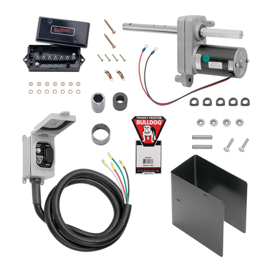
F3375
Powered Drive for Bulldog Jacks
Failure to follow these warnings and instructions may result
in property damage, serious bodily injury, and/or death.
rated capacity. If uncertain, contact Cequent
Trailer Products at 800-604-9466 or
www.cequentgroup.com
All welding must be performed by an AWS
certified welder.
Always replace bent, broken, or worn parts
before using this product.
To avoid accidental shock and/or damage to the
electrical system, disconnect the battery ground
cable before installation.
Warning: Failure to follow all installation instructions could
result in jack and/or powered drive failure.
Figure 1
Figure 2
Powered Drive - Single Speed Jack
Powered Drive - Two Speed Jack
(RE-10420) 3/06
Advertisement

Subscribe to Our Youtube Channel
Related Manuals for Cequent 1824200100


Summary of Contents for Cequent 1824200100
- Page 1 Failure to follow these warnings and instructions may result WARNING in property damage, serious bodily injury, and/or death. Purchaser/owner must ensure that product is rated capacity. If uncertain, contact Cequent installed according to these instructions. Pur- Trailer Products at 800-604-9466 or chaser/owner must not alter or modify product.
- Page 2 If the product does not comply with this warranty, We will replace the product without charge to You and within a reasonable time or, at Cequent's option, refund the purchase price.
- Page 3 SERVICE BULLETIN BULLDOG 12,000 LB. STATIC CAPACITY JACK WITH TWO SPEED PLANETARY GEAR BOX DISASSEMBLY INSTRUCTIONS PURPOSE TO DESCRIBE THE PROCEDURE FOR TAKING APART THE 183 SERIES PLANETARY GEAR JACKS TO ADD GEARS, CROSS SHAFT, PM HEX BUSHINGS, COMPRESSION SPRINGS, STRAIGHT PINS, OR SCREW AND NUT ASSEMBLY. REMOVE FOUR(4) NUTS ON PLANETARY GEAR AND SLIDE GEAR BOX OFF BOLTS INTACT.
Need help?
Do you have a question about the 1824200100 and is the answer not in the manual?
Questions and answers