Table of Contents
Advertisement
Quick Links
Advertisement
Table of Contents

Related Manuals for Chauvin Arnoux AEMC Instruments MR417


Summary of Contents for Chauvin Arnoux AEMC Instruments MR417
- Page 1 MR417 AC/DC CURRENT PROBE MR527 E N G L I S H User Manual...
- Page 2 ® 15 Faraday Drive • Dover, NH 03820 USA Tel: (800) 945-2362 or (603) 749-6434 • Fax: (603) 742-2346 This documentation is provided “as is,” without warranty of any kind, express, implied, or otherwise. Chauvin Arnoux , Inc. has ®...
- Page 3 Statement of Compliance Chauvin Arnoux , Inc. d.b.a. AEMC Instruments ® ® certifies that this instrument has been calibrated using standards and instruments traceable to international standards. We guarantee that at the time of shipping your instrument has met its published specifications.
-
Page 4: Table Of Contents
TABLE OF CONTENTS 1. INTRODUCTION ..................5 1.1 PRECAUTIONS FOR USE ................6 1.2 RECEIVING YOUR SHIPMENT ..............7 2. DESCRIPTION ..................8 2.1 INTERFACE ....................9 2.1.1 MR417....................9 2.1.2 MR527....................10 3. OPERATION ...................11 3.1 BATTERY INSTALLATION ................. 11 3.2 EXTERNAL POWER (OPTIONAL) ............11 3.3 TURNING THE INSTRUMENT ON ............ -
Page 5: Introduction
1. INTRODUCTION Thank you for purchasing the Current Probe Model MR417 or MR527. For best results from your instrument and for your safety, please read the following operating instructions carefully and comply with the precautions for use. This instrument is compliant with the IEC 61010-2-032 safety standards for voltages of 300V in measurement category IV or 600V in category III. -
Page 6: Precautions For Use
1.1 PRECAUTIONS FOR USE These instructions are intended to ensure the safety of users and proper operation of the instrument. Failure to observe these safety instructions may result in electric shock, fire, explosion, and desctruction of the instrument and/or installations. ■... -
Page 7: Receiving Your Shipment
1.2 RECEIVING YOUR SHIPMENT Upon receiving your shipment, make sure that the contents are consistent with the packing list. Notify your distributor of any missing items. It the equipment appears to be damaged, file a claim immediately with the carrier and notify the distributor at once, giving a detailed description of any damage. -
Page 8: Description
2. DESCRIPTION The Models MR417 and MR527 are clamp-on current probes that measure DC currents up to 1400A, AC currents up to 1000Arms (1400A peak), and combined AC+DC currents without opening the circuit that the current is flowing through. They indicate the shape and amplitude of the current measured in the form of a voltage. -
Page 9: Interface
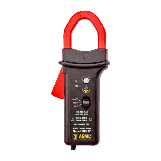
2.1 INTERFACE 2.1.1 MR417 Figure 1 (MR417) Item Functions Fixed (non-mobile) jaw Arrow indicating current flow direction Male BNC connector DC Zero button OL (overload) and ON indicators. ON is green when Auto Standby is enabled and yellow when it is disabled. P (Permanent mode) indicator. -
Page 10: Mr527
2.1.2 MR527 Figure 2 (MR527) Item Functions Fixed (non-mobile) jaw Arrow indicating current flow direction Male BNC connector DC Zero button OL (overload) and ON indicators. ON is green when Auto Standby is enabled and yellow when it is disabled. P (Permanent mode) indicator. -
Page 11: Operation
3. OPERATION 3.1 BATTERY INSTALLATION Before changing the battery, set the switch to OFF and remove the clamp from the circuit being measured. Using a screwdriver, remove the battery compartment cover (1) from the back of the housing (see Figure 3). Connect the battery to the snap-on connector (2), observing polarity. -
Page 12: Turning The Instrument On
3.3 TURNING THE INSTRUMENT ON To turn the clamp on, push the slide switch to the 1mV/A or 10mV/A setting: MR417 ■ 1mV/A corresponds to the 600A range. 10mV/A corresponds to the 60A range. ■ MR527 1mV/A corresponds to the 1400A range. 10mV/A corresponds to the 150A range. -
Page 13: Measurements
3.6 MEASUREMENTS 3.6.1 Making a Measurement After adjusting the DC Zero: 1. Press the clamp trigger to open the jaws. 2. Clamp the jaws around the conductor to be measured. Use the centering marks on the jaws to position the clamp around the conductor. If the measurement is for a power calculation, ensure the arrow on the clamp jaws (see Figures 1 and 2) points in the right direction of the current flow: source... -
Page 14: Specifications
4. SPECIFICATIONS 4.1 REFERENCE CONDITIONS Quantities of Influence Reference Conditions Temperature 73.4°F ± 9°F (23°C ± 5°C) Relative humidity 20 to 75% RH Position of the conductor Centered on the marks on the jaws Measurement frequency DC to 65Hz sine wave External electrical field Zero External DC magnetic field (Earth) - Page 15 Typical amplitude error curve at 60Hz MR417 Error (%) Current (A) MR527 Error (%) Current (A) Current Probe MR417 & MR527...
- Page 16 Typical amplitude error curve in DC MR417 Error (%) 1000 Current (A) MR527 Error (%) 1000 10000 Current (A) Current Probe MR417 & MR527...
- Page 17 Typical phase error curve at 60Hz MR417 Phase shift (°) Current (A) MR527 Phase shift (°) Current (A) Current Probe MR417 & MR527...
-
Page 18: Frequency Specifications, 1Mv/A Sensitivity
4.2.2 Frequency Specifications, 1mV/A Sensitivity Bandwidth -3db: DC to 30kHz Frequency 50Hz 400Hz 1kHz 10kHz Insertion MR417: 0.01mΩ MR417: 0.12mΩ MR417: 2.8mΩ <0.01mΩ impedance MR527: 0.05mΩ MR527: 0.14mΩ MR527: 3.4mΩ Typical amplitude error versus frequency curve at 60A MR417 Error (%) Frequency (Hz) MR527 Error (%) - Page 19 Typical phase versus frequency error curve at 60A MR417 Phase shift (°) 0° -10° -20° -30° -40° -50° -60° 1000 10000 100000 Frequency (Hz) MR527 Phase shift (°) 0° -10° -20° -30° -40° -50° -60° 1000 10000 100000 Frequency (Hz) Current Probe MR417 &...
-
Page 20: Electrical Specifications, 10Mv/A Sensitivity
Pulse Response (MR417 and MR527) Rise time (from 10 to 90%): ≤ 11μs Fall time (from 90 to 10%): ≤ 11μs AC noise on output: ≤ 1mV or 1A peak-to-peak Delay time at 10%: ≤ 10μs 4.2.3 Electrical Specifications, 10mV/A Sensitivity Output impedance: 215Ω... - Page 21 Typical amplitude error vs current curve at 60Hz MR417 Error (%) Current (A) MR527 Error (%) Current (A) Current Probe MR417 & MR527...
- Page 22 Typical amplitude error vs current curve in DC MR417 Error (%) Current (A) MR527 Error (%) Current (A) Current Probe MR417 & MR527...
- Page 23 Typical phase vs current error curve at 60Hz MR417 Phase shift (°) Current (A) MR527 Phase shift (°) Current (A) Current Probe MR417 & MR527...
-
Page 24: Frequency Specifications, 10Mv/A Sensitivity
4.2.4 Frequency Specifications, 10mV/A Sensitivity Bandwidth -3dB: DC to 30kHz Frequency 50Hz 400Hz 1kHz 10kHz Insertion MR417: 0.01mΩ MR417: 0.12mΩ MR417: 2.8mΩ <0.01mΩ impedence MR527: 0.05mΩ MR527: 0.14mΩ MR527: 3.4mΩ Typical amplitude error versus frequency curve at 30A MR417 Error (%) Frequency (Hz) MR527 Error (%) - Page 25 Typical phase versus frequency error curve at 100A MR417 Phase shift (°) 0° -10° -20° -30° -40° -50° -60° 1000 10000 100000 Frequency (Hz) MR527 Phase shift (°) 0° -10° -20° -30° -40° -50° -60° 1000 10000 100000 Frequency (Hz) Current Probe MR417 &...
-
Page 26: Operating Limits
Pulse Response (MR417 and MR527) Rise time (from 10 to 90%): ≤ 11μs Fall time (from 90 to 10%): ≤ 11μs AC noise on output: ≤ 3mV or 0.3A Delay time at 10%: ≤ 10μs Square wave response curves 4.3 OPERATING LIMITS (MR417 AND MR527) •... -
Page 27: Variations In The Range Of Use
4.4 VARIATIONS IN THE RANGE OF USE Error in % of reading Quantity of Range of influence influence Typical Maximum Drift of the zero 14 to 131°F ± 100mA/°C Temperature (-10 to +55°C) Drift of the gain Relative humidity 10 to 85% RH 0.5% 10 to 400Hz Frequency... -
Page 28: Power Supply
4.5 POWER SUPPLY The instrument is powered by a 9V battery (type 6LR61, 6LF22, or NEDA 1604). The average battery life is 50 hours with an alkaline battery. The instrument can also be powered by an external supply (5VDC, 100mA) via the type B micro-USB connector. -
Page 29: Mechanical Specifications
4.7 MECHANICAL SPECIFICATIONS MR417 Dimensions (L x W x H): 8.8 x 3.8 x 1.7in (224 x 97 x 44mm) Weight: approximately 15.5oz (440g) Cable: 6.6ft (2m) Maximum Conductor Size: Cables: One 1.18in (30mm) or two 0.94in (24mm) Bus Bar: One 1.97 x 0.39in (50 x 10mm) or two 1.23 x 0.39in (31.5 x 10mm) or three 0.98 x 0.31in (25 x 8mm) Figure 5 Current Probe MR417 &... - Page 30 MR527 Dimensions (L x W x H): 9.3 x 3.8 x 1.7in (237 x 97 x 44mm) Weight: approximately 18.3oz (520g) Cable: 6.6ft (2m) Maximum Conductor Size: Cables: One 1.5in (39mm) or two 1in (25.4mm) Bus Bar: One 1.97 x 0.49in (50 x 12.5mm) or two 0.98 x 0.2in (25 x 5mm); 1.24 x 0.30in (31.5 x 10mm) or three 0.98 x 0.31in (25 x 8mm) Figure 6 Current Probe MR417 &...
-
Page 31: Housing Protection
4.7.1 Housing Protection Protection index: • IP 40 per IEC 60529 • IK 06 per IEC 62262 Drop test per IEC/EN 61010-2-032 or BS EN 61010-2-032. 4.8 SAFETY SPECIFICATIONS Electrical Conformity to International Standards: This instrument is compliant with IEC/EN 61010-2-032 or BS EN 61010-2-032, 300V category IV and 600V category III. -
Page 32: Maintenance
5. MAINTENANCE Except for the battery, the instrument contains no parts that can be replaced by personnel who have not been specially trained and accredited. Any unauthorized repair or replacement of a part by an “equivalent” may gravely impair safety. 5.1 CLEANING •... -
Page 33: Repair And Calibration
Please write the CSA# on the outside of the shipping container. If the instrument is returned for calibration, we need to know if you want a standard calibration, or a calibration traceable to N.I.S.T. (includes calibration certificate plus recorded calibration data). Chauvin Arnoux , Inc. d.b.a. AEMC Instruments ®... -
Page 34: Limited Warranty
Service Department (see address below), then return the instrument along with the signed CSA Form. Please write the CSA# on the outside of the shipping container. Return the instrument, postage or shipment pre-paid to: Chauvin Arnoux , Inc. d.b.a. AEMC Instruments ®... - Page 35 NOTES:...
- Page 36 01/22 99-MAN 100522 v6 Chauvin Arnoux , Inc. d.b.a. AEMC Instruments ® ® 15 Faraday Drive • Dover, NH 03820 USA • Phone: (603) 749-6434 • Fax: (603) 742-2346 www.aemc.com...
Need help?
Do you have a question about the AEMC Instruments MR417 and is the answer not in the manual?
Questions and answers