Advertisement
Quick Links
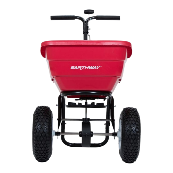
MODEL # F80/F80H
Visit our
EarthWay
website to see the
assembly video
HELPFUL HINTS
Read the directions before assembly.
If your spreader does not spread evenly, be sure "FRONT" on the GEARBOX points to the front of the spreader. The
impeller must turn clockwise when pushing forward. Reversing the GEARBOX during assembly will cause issues.
Your spreader is calibrated for three miles per hour, which is a brisk walking speed. Slower or faster speeds will
change the spread pattern. Wet fertilizer will also change the spread pattern and flow rate. Do not use powdered
materials as it will damage the gearbox.
Gears are permanently lubricated at the factory. Do not open the GEARBOX or dirt may enter.
F80_REVMARCH2024
FLEX-SELECT Series
Broadcast Spreader
ASSEMBLY INSTRUCTIONS
SIDE SPREAD CONTROL
Patent U.S. 10,993,368
Your EarthWay spreader includes a patented
feature to prevent fertilizer from being spread
to the left side. To activate this feature, slide the lever
below the hopper to the back (if standing behind the
spreader) and position the left wheel 6ʺ-12ʺ from your
sidewalk or border. This will not waste fertilizer like
competitor designs that leave 7X the fertilizer inside the
wheels from blocking material leaving the impeller.
PRIOR TO ASSEMBLY, YOU WILL NEED:
7/16ʺ Wrench
Ratchet
7/16" Socket Pliers
PAGE 1
Advertisement

Related Manuals for EarthWay F80H


Summary of Contents for EarthWay F80H
- Page 1 ASSEMBLY INSTRUCTIONS SIDE SPREAD CONTROL Visit our Patent U.S. 10,993,368 EarthWay Your EarthWay spreader includes a patented website to see the feature to prevent fertilizer from being spread assembly video to the left side. To activate this feature, slide the lever below the hopper to the back (if standing behind the spreader) and position the left wheel 6ʺ-12ʺ...
- Page 2 Assembly and Operation Instructions SPREADER ASSEMBLY INSTRUCTIONS Step 1: Remove the spreader and parts from the Axle Bearing carton and arrange on the floor. Step 2: Remove HOG RING and SPRING CLIP from Notch AXLE and make sure the AXLE is installed correctly. The side that has the hole closest to the end of the AXLE should be located on the left side of the spreader (facing the back).
- Page 3 Assembly and Operation Instructions Step 9: Now remove the PIVOT BRACKET from THE LOWER HANDLES. Keep the 1/4 -20 x 2” bolts and locknuts for use in reinstallation. Step 10: Install HANDLE SHAFT INTO LOWER HANDLES and then reattach the PIVOT BRACKET assembly as shown onto the LOWER HANDLES using two 1/4 -20 x 2”...
- Page 4 Assembly and Operation Instructions Step 13: Insert PIVOT ROD into SHUT-OFF PLATE as shown. Turn to lock in place. Thighten all hardware. Step 14: Next, insert other end of PIVOT ROD into PIVOT BRACKET assembly as shown. Turn to lock in place.
-
Page 5: Tray Installation
Assembly and Operation Instructions TRAY INSTALLATION *Installation instructions may vary depending on the tray you are using. Please read all instructions carefully. Step 1: Install TRAY from the top downwards into the hopper (see figure) positioning the center hole of the tray over the PINION SHAFT from the gear box with the PIVOT ROD through the bottom of the hopper and facing toward the spreader’s handlebar. - Page 6 Assembly and Operation Instructions F80_REVMARCH2024 PAGE 6...
- Page 7 Assembly and Operation Instructions SPREADER CALIBRATION INSTRUCTIONS HIGH-OUTPUT and LOW-OUTPUT TRAY: Make sure the drop holes in the bottom of the hopper are FULLY CLOSED when the RATE CONTROL LEVER is resting on Stop #0. If the shut-off is not set correctly, please adjust CONTROL ROD at the PIVOT to position the shut-off for FULLY CLOSED at position at the Stop #0 on the RATE CONTROL LEVER.
- Page 8 Assembly and Operation Instructions HANDLE ADJUSTMENT INSTRUCTIONS TALL OPERATOR CONFIGUATION – with the four handle holes, use the bottom two holes for the guage and use the top two holes for the spacer. F80_REVMARCH2024 PAGE 8...
-
Page 9: How To Order Parts
Assembly and Operation Instructions HOW TO ORDER PARTS Call or Email: TURF DEPOT 800-305-9255 or earthway@turfdepot.com F80_REVMARCH2024 PAGE 9... - Page 10 Assembly and Operation Instructions F80/F80H Broadcast Spreader Parts List PART # DESCRIPTION 12110 IMPELLER 9" ROUND DISHED F60333 GEAR BOX ASSEMBLY FLEX -SELECT 12148 AXLE BEARING 12152 AXLE BUSHING 24500 AXLE 33115 HOG RING 33113 SPRING CLIP 25228 CROSS BRACE...
-
Page 11: Customer Service
EarthWay. Due to the corrosive nature of most fertilizers and ice melt products, EarthWay Products, Inc. makes no warranty against and specifically excludes part(s) or product degradation or failure due to corrosion or its effects .
Need help?
Do you have a question about the F80H and is the answer not in the manual?
Questions and answers