Table of Contents
Advertisement
Quick Links
Contents
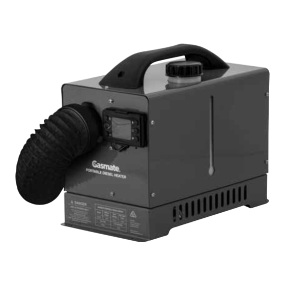
the heater unit
PORTABLE
DIESEL HEATER
SERVICE MANUAL
Important: Retain these instructions for future use.
Gasmate
Sitro Group Australia Pty Ltd www.gasmate.com.au
Aber Living Ltd, N.Z www.gasmate.co.nz
Model No. GM20-425
2
3
chamber
5
exterior surfaces
7
9
10
is a registered trademark of:
®
11
12
19
19
19
04722 03/24
Advertisement
Table of Contents

Subscribe to Our Youtube Channel
Related Manuals for Gasmate GM20-425


Summary of Contents for Gasmate GM20-425
-
Page 1: Table Of Contents
How to remove and clean the air filter Flushing the fuel lines How to change the fuel pump Important: Retain these instructions for future use. Gasmate is a registered trademark of: ® Sitro Group Australia Pty Ltd www.gasmate.com.au Aber Living Ltd, N.Z www.gasmate.co.nz 04722 03/24... -
Page 2: How To Remove The Outer Metal Cover Of
HOW TO REMOVE THE OUTER METAL COVER OF THE HEATER UNIT HOW TO REPLACE THE GLOW PLUG TOOLS REQUIRED: PARTS & TOOLS REQUIRED: After removal of the outer metal cover of the heater, you can access the heater unit. Replacement of the glow plug can be done without removing the heater unit from the case, however you might find it easier to remove it if doing additional work. -
Page 3: How To Replace The Temperature Sensor
HOW TO REPLACE THE GLOW PLUG - Continued HOW TO REPLACE THE TEMPERATURE SENSOR PARTS REQUIRED: 4. Carefully insert the new Glow Plug into the opening and screw in. NOTE: Be very careful to not cross- thread when screwing it in and to rotate the harness wires around with the glow plug so they do not get twisted and damaged. -
Page 4: How To Replace The Pcb
HOW TO REPLACE THE TEMPERATURE SENSOR - Continued HOW TO REPLACE THE PCB 4. Place the new sensor in place and secure with the retaining clip. PARTS & TOOLS REQUIRED: 5. Route the wire back to the PCB and plug it into the PCB. 6. -
Page 5: How To Remove And Clean The Air Filter
HOW TO REPLACE THE PCB - Continued HOW TO REMOVE AND CLEAN THE AIR FILTER 5. Take the new PCB and insert the connectors After removal of the outer metal cover of the PARTS & TOOLS REQUIRED: for the glow plug and sensors and control. heater, you can access the heater unit. -
Page 6: How To Change The Fuel Pump
HOW TO CHANGE THE FUEL PUMP MAIN PARTS OF HEATER UNIT PARTS & TOOLS REQUIRED: Fuel pump Phillips head screwdriver After removal of the outer metal cover of the heater, you can access the heater unit. Before removing or replacing the fuel pump, it is recommended to first empty the fuel tank and purge the fuel from the fuel lines to prevent spillage during this work. -
Page 7: How To Disassemble The Combustion
HOW TO DISASSEMBLE THE COMBUSTION CHAMBER HOW TO DISASSEMBLE THE COMBUSTION CHAMBER - Continued TOOLS REQUIRED: 4. Unscrew the allen bolt securing the PCB assembly in place. Carefully lift up the PCB and unplug the connectors for the glow plug, sensors and control before removing it completely. 5. - Page 8 HOW TO DISASSEMBLE THE COMBUSTION CHAMBER - Continued HOW TO DISASSEMBLE THE COMBUSTION CHAMBER - Continued 6. Remove the 3 bolts securing the combustion chamber to the heat exchanger then slide it out. Then, 8. Insert the clean (or new) Atomizing net using the special insertion tool from the Service Toolkit. If using the hook tool from the Service Toolkit carefully remove the atomising net from the combustion replacing the inner combustion chamber gasket (Gasket A), ensure the old one is removed and the chamber body.
- Page 9 HOW TO DISASSEMBLE THE COMBUSTION CHAMBER - Continued HOW TO DISASSEMBLE THE COMBUSTION CHAMBER - Continued 10. The Glow plug can be installed using the special tool from the Service Toolkit. As with removal, be 12. Attach the bolt to secure the PCB assembly in place. very careful not to twist the wires coming out of the Glow plug when tightening it in place.
-
Page 10: Removing Dust And Debris From The
HOW TO DISASSEMBLE THE COMBUSTION CHAMBER - Continued REMOVING DUST AND FLUSHING THE FUEL LINES DEBRIS FROM THE EXTERIOR 14. Attach the top cover of the heater. SURFACES Flushing the fuel lines of your diesel heater is the Connect the main harness connector. Install the heater unit into the outer case, tighten the bolts and final step in cleaning the fuel system, ensuring attach the exhaust and combustion air intake pipes and tighten the clamps. - Page 11 Important: Retain these instructions for future use. For any queries or assistance call Customer Service (Australia Only) 1300 174 876 Hours of operation: Monday to Friday 8am - 5pm EST Do not return to place of purchase. Keep your purchase receipt, this will be required to make any claims under the 1 year warranty.
Need help?
Do you have a question about the GM20-425 and is the answer not in the manual?
Questions and answers