Table of Contents
Advertisement
Quick Links
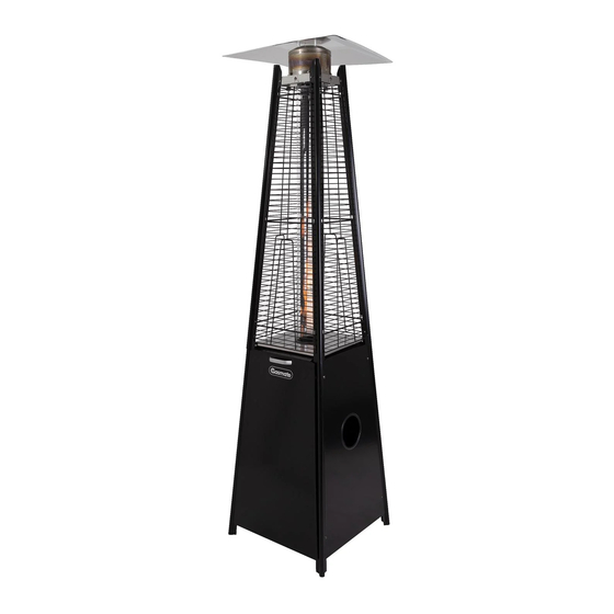
FLUX
HEATER
Model No. GM124-025
The ideal solution to extend your outdoor
entertaining season
Maximum output 33.5MJ/h
Piezo ignition for easy lighting
Adjustable heat output
Operates for approximately 14 hours on a properly
filled 9kg cylinder
Wheels for portability
Includes a safety 'tip-over' switch
Flame safe-guard system for enhanced safety
Complete with hose and regulator
Assembled dimensions (mm): 490W x 1900H x 490D
12 month warranty
Approved to NZ Standards
Gasmate® is a registered trademark of: Sitro Group Australia Pty Ltd www.gasmate.com.au
Important: Retain these instructions for future use.
WARNING
Improper installation, adjustment, alteration, service
or maintenance can cause injury or property
damage.
Read the instructions thoroughly before installing or
servicing this equipment.
FOR OUTDOOR USE ONLY
Aber Living - Hamilton, N.Z. www.gasmate.co.nz
5104-04/19
Advertisement
Table of Contents

Related Manuals for Gasmate FLUX GM124-025


Summary of Contents for Gasmate FLUX GM124-025
- Page 1 12 month warranty FOR OUTDOOR USE ONLY Approved to NZ Standards Important: Retain these instructions for future use. Gasmate® is a registered trademark of: Sitro Group Australia Pty Ltd www.gasmate.com.au Aber Living - Hamilton, N.Z. www.gasmate.co.nz 5104-04/19...
-
Page 2: Important Safety Rules
INSTALLATION, OPERATION & MAINTENANCE INSTRUCTIONS Prior to assembling your appliance, the following must be reviewed. Compliance with the following should result IMPORTANT SAFETY RULES in satisfactory heater operation. This instruction manual should be retained for future reference. The installation This appliance must only be used in a well ventilated must conform with local codes or authority having area. - Page 3 d. The flame should be visually checked whenever Any modification to the heater not described in the heater is operated. If flames extend beyond surface installation instructions may compromise the safety of of the chimney or black soot is accumulating on this appliance.
-
Page 4: Parts List
PARTS LIST 4. Lower Support Leg. 80cm Long 5. Upper Support 1. Middle Plate 2. Control Box 3. Bottom Panel Rubber Foot Post 7. Lower Plate 9. Radiant Head Pre-assembled in Pre-assembled in 6. Upper Plate Middle Plate 8. Glass Tube Upper Plate 10. - Page 5 ASSEMBLY INSTRUCTIONS Note: Remove any transit protection material. Tools required Phillips head screw driver and 2 adjustable spanners. STEP 1 The lower support leg (4) is identified by a rubber foot at the bottom. Remove the five screws (15) from each leg, using them to attach the bottom panel (3) and middle plate (1) from the inside.
- Page 6 ASSEMBLY INSTRUCTIONS STEP 4 Attach the control box (2) to the underside of the middle plate (1) with the controls facing the magnets, using 4 screws (15) from underneath. Unscrew and remove the igniter cap, insert a ‘AA’ battery with the + facing outwards, then re-attach the cap.
- Page 7 ASSEMBLY INSTRUCTIONS STEP 6 Attach the reflector (10) to the studs on the radiant head (9) using the washers and wing nuts supplied. STEP 7 Attach the four guards (11) by aligning the hooks with the slots in the upper support posts (5) and secure at the top with the bracket (12) and screw supplied.
- Page 8 ASSEMBLY INSTRUCTIONS STEP 8 Attach the side and back panels (13) using the 4 screws (15) supplied per panel. STEP 9 Connect the hose to the hose connector on the underside of the control box (2). Leak test all connections using a soapy water solution.
-
Page 9: Lighting Instructions
LIGHTING INSTRUCTIONS Warning: White smoke may appear round the burner head during the first minutes of initial firing. 1. Check and ensure that an AA battery is inside the ignition chamber and has power. Ensure the anode (+) LIGHT HIGH faces outside. -
Page 10: Troubleshooting
TROUBLE SHOOTING Problem Possible Causes Solution Gas valve may be OFF Turn the gas valve ON LPG cylinder empty Refill LPG cylinder Main burner Orifice blocked Clean or replace orifice will not light Air in supply system Purge air from lines Loose connection Check all fittings Debris around pilot... -
Page 11: Safe Appliance Locations
SAFE APPLIANCE LOCATIONS This appliance shall only be used in an above ground Within a partial enclosure that includes an overhead open-air situation with natural ventilation, without cover and no more than two walls stagnant areas, where gas leakage and products of (see Example 2 &...
Need help?
Do you have a question about the FLUX GM124-025 and is the answer not in the manual?
Questions and answers