Sign In
Upload
Download
Table of Contents
Contents
Add to my manuals
Delete from my manuals
Share
URL of this page:
HTML Link:
Bookmark this page
Add
Manual will be automatically added to "My Manuals"
Print this page
×
Bookmark added
×
Added to my manuals
Manuals
Brands
G&D Manuals
Control Unit
DVI-U-CPU
Installation and operation manual
G&D DVI-U-CPU Installation And Operation Manual
Computer and console modules
Hide thumbs
1
2
3
Table Of Contents
4
5
6
7
8
9
10
11
12
13
14
15
16
17
18
19
20
21
22
23
24
25
26
27
28
29
30
31
32
33
34
35
36
37
38
39
40
41
42
43
44
45
46
47
48
49
50
51
52
53
54
55
56
57
58
59
60
61
62
63
64
65
66
67
68
69
70
71
72
73
74
75
76
77
78
79
80
81
82
83
84
85
86
87
88
89
90
91
92
93
94
95
96
97
98
99
100
101
102
103
104
105
106
107
108
109
110
111
112
113
114
115
116
117
118
119
120
121
122
123
124
125
126
127
128
129
130
131
132
133
134
135
136
137
138
139
140
141
142
143
144
145
146
147
148
149
150
151
152
153
154
155
156
157
158
159
160
161
162
163
164
165
166
167
168
169
170
171
172
173
174
175
176
177
178
179
180
181
182
183
184
185
186
187
188
189
190
191
192
193
194
195
196
197
198
199
200
201
202
203
204
page
of
204
Go
/
204
Contents
Table of Contents
Bookmarks
Table of Contents
Table of Contents
Safety Guidelines
Chapter 1: Computer Modules
Computer Module "DVI-U-CPU
Computer Module "DVI-U-CPU-UC
Computer Module "DVI-U-CPU-MC2
Computer Module "DVI-U-CPU-MC2-UC
Computer Module "DVI-U-CPU-Fiber
Computer Module "DVI-U-CPU-Fiber-UC
Computer Module "DL-DVI-U-CPU
Computer Module "DL-DVI-U-CPU-UC
Computer Module "DL-DVI-U-CPU-Fiber
Computer Module "DL-DVI-U-CPU-Fiber-UC
Computer Module "DP-U-CPU
Computer Module "DP-U-CPU-UC
Computer Module "DVI-I-U-CPU
Computer Module "DVI-I-U-CPU-UC
Computer Module "DVI-I-U-CPU-Fiber
Computer Module "DVI-I-U-CPU-Fiber-UC
Computer Module "VGA-U-CPU-UC
Chapter 2: Console Modules
Console Module "DVI-U-CON
Console Module "DVI-U-CON-MC2
Console Module "DVI-U-CON-MC4
Console Module "DVI-U-CON-2
Console Module "DVI-U-CON-Fiber
Console Module "DVI-U-CON-Fiber-MC2
Console Module "DVI-U-CON-Fiber-MC4
Console Module "DVI-U-CON-2-Fiber
Console Module "DP-U-CON
Console Module "DP-U-CON-2
Chapter 3: Generic HID
Enabling/Disabling the Console Module's Generic HID Mode
Enabling/Disabling the Computer Module's Generic HID Mode
Chapter 4: Extender Mode
Opening the OSD in Extender Mode
Configuration
Advertisement
Quick Links
1
Console Module "DVI-U-Con
Download this manual
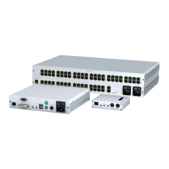
G&D Computer and Console Modules
EN
Installation and Operation
Devices with integrated USB
A9200138-1.21
Table of
Contents
Previous
Page
Next
Page
1
2
3
4
5
Advertisement
Table of Contents
Need help?
Do you have a question about the DVI-U-CPU and is the answer not in the manual?
Ask a question
Questions and answers
Related Manuals for G&D DVI-U-CPU
Control Unit G&D DP-HR Installation And Operations
Target and user modules (192 pages)
Control Unit G&D DP-HR-U Installation And Operations
Target and user modules (196 pages)
Control Unit G&D DP-HR-CPU Installation And Operation Manual
Computer and console modules (200 pages)
Control Unit G&D DVI-CPU Installation And Operation Manual
Computer and console modules (216 pages)
Control Unit G&D DP-CPU Installation And Operation Manual
Computer and console modules (216 pages)
Control Unit G&D DVI-CON Installation And Operation Manual
Computer and console modules (216 pages)
Control Unit G&D DP-CON Installation And Operation Manual
Computer and console modules (216 pages)
Control Unit G&D DP-HR-U-CPU Installation And Operation Manual
Computer and console modules (204 pages)
Control Unit G&D DP-U-CPU Installation And Operation Manual
Computer and console modules (204 pages)
Control Unit G&D DVI-U-CON Installation And Operation Manual
Computer and console modules (204 pages)
Control Unit G&D RemoteAccess-IP-CPU Installation Manual
(52 pages)
Control Unit G&D VisionXS-F-DVI-I Installation & Operation Manual
(248 pages)
Control Unit G&D U2+R Installation And Operations
(56 pages)
Control Unit G&D HDM-CPU Series Installation And Operation Manual
Computer modules (76 pages)
This manual is also suitable for:
Dvi-u-cpu-uc
Dvi-u-cpu-mc2
Dvi-u-cpu-mc2-uc
Dvi-u-cpu-fiber
Dvi-u-cpu-fiber-uc
Dl-dvi-u-cpu
...
Show all
Dl-dvi-u-cpu-uc
Dl-dvi-u-cpu-fiber
Dl-dvi-u-cpu-fiber-uc
Dp-u-cpu
Dp-u-cpu-uc
Dvi-i-u-cpu
Dvi-i-u-cpu-uc
Dvi-i-u-cpu-fiber
Dvi-i-u-cpu-fiber-uc
Vga-u-cpu-uc
Dvi-u-con
Dvi-u-con-mc2
Dvi-u-con-mc4
Dvi-u-con-2
Dvi-u-con-fiber
Dvi-u-con-fiber-mc2
Dvi-u-con-fiber-mc4
Dvi-u-con-2-fiber
Dp-u-con
Dp-u-con-2
Table of Contents
Print
Rename the bookmark
Delete bookmark?
Delete from my manuals?
Login
Sign In
OR
Sign in with Facebook
Sign in with Google
Upload manual
Upload from disk
Upload from URL


Need help?
Do you have a question about the DVI-U-CPU and is the answer not in the manual?
Questions and answers