Advertisement
Quick Links
Advertisement

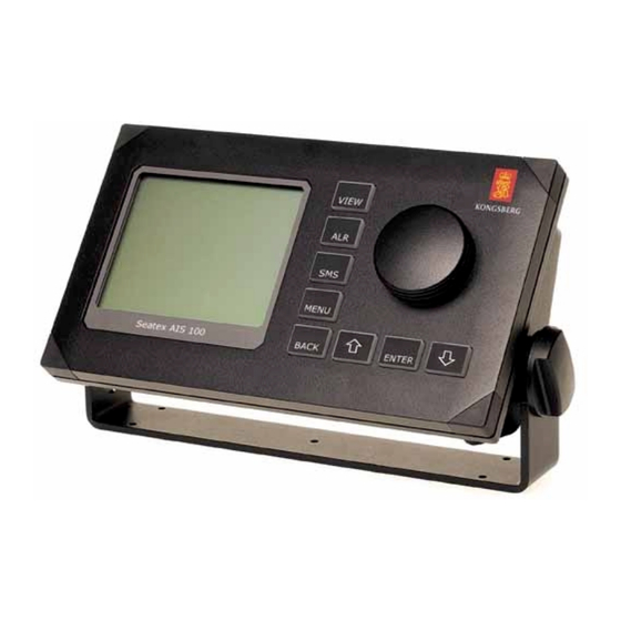
Summary of Contents for Kongsberg Seatex AIS 100
- Page 1 Seatex AIS 100 Quick Start Guide GNSS Satellites AIS Base Station AIS VHF Link AIS VHF Link VTS Centre Kongsberg Seatex AS Pirsenteret N-7462 Trondheim Norway Telephone: +47 73 54 55 00 Facsimile: +47 73 51 50 20 E-mail: firmapost@kongsberg-seatex.no...
-
Page 2: Abbreviations And Acronyms
Seatex AIS 100 Quick Start Guide, rev. 0 Introduction Introduction Purpose This document is intended used in connection with installation, configuration and final verification of the AIS 100. This document gives a brief description of the different components, how to connect the components, start up and how to configure the unit after start-up. - Page 3 Seatex AIS 100 Quick Start Guide, rev. 0 Installation, configuration and functionality Installation, configuration and functionality Equipment A Seatex AIS 100 consists of the following parts: • 1 AIS 100 unit • 1 GPS antenna • 1 GPS antenna bracket •...
-
Page 4: Installation Procedure
Seatex AIS 100 Quick Start Guide, rev. 0 Installation, configuration and functionality In addition to the above listed equipment, antenna cables must be included. The total attenuation of the GPS antenna cable should be less than 10 dB as higher attenuation may degrade the quality and the accuracy of the position data. - Page 5 Seatex AIS 100 Quick Start Guide, rev. 0 Installation, configuration and functionality 5. Mount the VHF antenna to a high mast or railing away from interfering high power energy sources and at least 3 meters from, and out of, the transmitting beam, see Figure 2.
- Page 6 Seatex AIS 100 Quick Start Guide, rev. 0 Installation, configuration and functionality The LED indicators are described in the table below. Colour Description Transmitter off. Long green Transmitting on DSC channel (channel 70). Amber blink Transmitting on channel B. Green blink Transmitting on channel A.
- Page 7 Seatex AIS 100 Quick Start Guide, rev. 0 Installation, configuration and functionality 11. Check, and if necessary change, the baud rate for the external serial Antenna location ports, which are going to be used. The Pilot, PI, Long Range, Sensor 1, Sensor 2, Sensor 3 and the Com1ports are available.
-
Page 8: Commissioning Report
Seatex AIS 100 Quick Start Guide, rev. 0 Commissioning report Commissioning report Installation Not OK Power from emergency supply Pilot plug installed PWR LED indicator green TX LED indicator green & amber blink MSG LED indicator green & amber blink...


Need help?
Do you have a question about the Seatex AIS 100 and is the answer not in the manual?
Questions and answers