Table of Contents
Advertisement
Advertisement
Table of Contents

Related Manuals for Kongsberg Simrad IS12 Mega


Summary of Contents for Kongsberg Simrad IS12 Mega
- Page 1 A L W A Y S T H E F O R E F R O N T T E C H N O L O G Y...
- Page 3 Instruction Manual Simrad IS12 Mega Instrument...
- Page 4 IS12 Mega © 2002 Simrad Ltd The technical data, information and illustrations contained in this publication were to the best of our knowledge correct at the time of going to print. We reserve the right to change specifications, equipment, installation and maintenance instructions without notice as part of our policy of continuous development and improvement.
-
Page 5: Table Of Contents
Instruction Manual CONTENTS GENERAL 1.1 Introduction ........6 1.2 IS12 Network System . -
Page 6: Introduction
IS12 Mega 1 GENERAL 1.1 Introduction The Simrad IS12 System is a flexible modular series of instru- ments that offer large, clear displays, easy to operate functions and robust, weatherproof construction. The IS12 Mega is a multifunction data repeater that can display information from any master IS12 unit in the system, or act as an NMEA repeater. -
Page 7: Is12 Network System
Instruction Manual 1.2 IS12 Network System The IS12 system is built around a high speed bus networking system that allows instruments to be easily interconnected and share data. All units are interconnected and powered using a standard sin- gle cable (Fig 1.2) - COMPASS Tx WIND Tx MEGA... -
Page 8: Operation
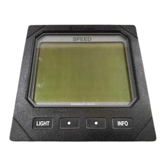
IS12 Mega 2 OPERATION 2.1 General The IS12 Mega is a large digit multifunction repeater that can display data either from any IS12 master unit (Fig 2.1) - MEGA MEGA MEGA IS12 SPEED IS12 DEPTH IS12 WIND Fig 2.1 - Mega displays as IS12 system repeaters or from other equipment via NMEA0183 (Fig 2.2) - Fig 2.2 - Mega displays as NMEA repeaters E04252... - Page 9 Instruction Manual Press the INFO key to cycle through the data pages on the Mega instrument - Boat Speed* ¬ Log ¬ Trip ¬ Water Temperature ¬ Average Speed ¬ Maximum Speed ¬ Race Start Timer ¬ Depth* ¬ Shallow Alarm Setting ¬ Deep Alarm Setting ¬...
- Page 10 IS12 Mega Individual data pages can be switched off if necessary to avoid having to cycle through pages that have no incoming data - refer to section 3.1 for further details. MEGA MEGA MEGA MEGA • • • • • •...
- Page 11 Instruction Manual MEGA MEGA MEGA • • • • • • LIGHT INFO LIGHT INFO LIGHT INFO MEGA MEGA MEGA • • • • • • INFO INFO INFO LIGHT LIGHT LIGHT MEGA MEGA MEGA • • • • • •...
-
Page 12: Data
IS12 Mega 2.2 Data Page Information 2.2.1 Calibration & Settings No control or calibration of the incoming data is possible. To adjust any settings (eg depth alarms) or activate any functions (eg race countdown timer), use the relevant master unit. 2.2.2 Display Units The units of measurement used on the data pages are dictated by the incoming data - to change, select the required display... -
Page 13: Apparent & True Wind Angle
Instruction Manual 2.2.5 Apparent & True Wind Angle There are two display options for each of the above pieces of data. The first is a standard 0-180º display which shows the wind angle relative to the boat and the current tack (Fig 2.6) - MEGA •... -
Page 14: Vmg (Velocity Made Good)
IS12 Mega When showing the close hauled wind angle, the graphic on the left of the display indicates the direction of the wind. When sailing close hauled, the digits show the wind angle measured from the bow of the boat (Fig 2.8) - Close hauled, port tack Close hauled, starboard tack Fig 2.8 - Wind direction indicator - Close Hauled... -
Page 15: Xte (Cross Track Error)
Instruction Manual 2.2.7 XTE (Cross Track Error) The Cross Track Error (XTE) is the amount of deviation from the ideal track to the target waypoint displayed as a distance from the track. The arrow on the top line of the display indicates the direction of the error from the track (Fig 2.11) - WPT 2 MEGA... -
Page 16: Remote Control Option
IS12 Mega Press the (• RIGHT) key to increase the brightness (max 5), (• LEFT) to decrease it (min 1), (INFO) to accept the select- ed brightness or (LIGHT) to turn the backlighting off. NOTE While the backlighting is on, the lamp icon ( ) will be shown on the bottom left of the display. -
Page 17: Calibration
Instruction Manual 3 CALIBRATION To protect the calibration functions, these are held in a hidden menu. To enter calibration mode, press and hold the LIGHT key (Fig 3.1) - • • LIGHT INFO MEGA • • LIGHT INFO Fig 3.1 - Entering Calibration Mode Once in calibration mode, pressing the (•... - Page 18 IS12 Mega 3.1 Page Configuration To avoid having to scroll through data pages that have no incoming information, or to set the Mega to display only select- ed information available, individual data pages can be disabled using this function. Enter calibration mode - the display will show PAGES CAL - and press (INFO) .
-
Page 19: Operation Modes
Instruction Manual 3.2 Operation Modes There are two modes of operation for the Mega instrument depending on the installation and equipment it is to be used alongside. 3.2.1 IS12 Mode (Mode 1) This is for use when the Mega is to be used as part of an IS12 instrument system. -
Page 20: Nmea Mode
IS12 Mega 3.2.2 NMEA Mode (Mode 2) This mode should be selected if the Mega instrument is to be used as an NMEA data repeater with no IS12 master units. In this mode, the Mega will display the following data - - NMEA0183 instrument data - NMEA0183 navigational data In this mode only the NMEA terminals are used to link the... -
Page 21: Local & Network Backlighting
Instruction Manual 3.3 Local & Network Backlighting The backlighting can be set so that any changes made are duplicated across the system (Network), or so that any changes are limited to the specific instrument only (Local). The IS12 instruments are set to Networked lighting as default. Enter calibration mode, press once (the display will show LIGHT CAL) and press... -
Page 22: Disable Remote Control
IS12 Mega 3.4 Disable Remote Control On some installations which includes the IS12 Remote Control, it may be more convenient to limit remote control access to only some instruments on the network - for example on a fly- bridge power boat with a set of instruments on both steering stations, it would not be desirable to be able to control the instruments on the flybridge (Fig 3.5) - Flybridge... -
Page 23: Installation
Instruction Manual 4 INSTALLATION 4.1 Instrument Head Installation All IS12 instrument heads are a standard 110 x 110mm (4.3x 4.3in) size, and can be mounted either from the front or the rear. 4.1.1 Front Mounting Fig 4.1 - Front Mounting 65mm (2.5in) Front mounting (Fig 4.1) is the standard method of fitting and minimum... - Page 24 IS12 Mega The instrument is 110mm (4.33 in) square, but a distance of at least 6mm (0.25 in) should be allowed between adjacent units for the protective instrument cover supplied. NOTE Long term exposure to direct sunlight can damage the liquid crystal display if left unprotected when not in use - always use the instrument cover supplied.
-
Page 25: Rear Mounting
Instruction Manual 4.1.2 Rear Mounting When the instrument is rear mounted, only the display can be seen - the main body of the instrument, including the keypad is hidden behind the panel. This is a more elegant method of installation, but does require precise cutting of the apertures into the bulkhead or dashboard. -
Page 26: Electrical Installation - Is12 Mode
IS12 Mega 4.2 Electrical Installation - IS12 Mode (Mode 1) IS12 instruments are ‘daisy chained’ together, with each instru- ment linking to the previous one by a single cable carrying power and data (Fig 4.7). The cable plugs into either of the two circular network ports on the rear of the instrument. -
Page 27: Network Termination
Instruction Manual 4.2.1 Network Termination The IS12 system is based around a high speed data bus net- work. Although this is very robust, on very large or complex systems with many instruments the system may need to be properly terminated to ensure the integrity of the network. For this purpose a network terminator (Fig 4.9) is supplied with some IS12 instruments, including the IS12 Mega. -
Page 28: Nmea Input/Output
IS12 Mega 4.2.2 NMEA Input/Output The Mega instrument features an NMEA0183 input and output Fold wire Ensure bare wires end back are not visible and is interfaced to external equipment using the crimp termi- nals supplied. To ensure a good connection when fitting the terminals to the interface cable, fold back the exposed wires over the insulation before inserting into the terminal (Fig 4.11). -
Page 29: Electrical Installation - Nmea Mode
Instruction Manual 4.3 Electrical Installation - NMEA Mode (Mode 2) The Mega instrument can be used as a stand alone (i.e not part of an IS12 system) repeater in conjunction with any third-party equipment outputting/receiving the correct NMEA0183 for- mat. If using the Mega in this way, the operation mode should be set to NMEA (2) - see section 3.2. -
Page 30: Electronic Interference Suppression
IS12 Mega When in NMEA Mode the Mega can receive and display instrument and navigational data input via the NMEA IN ter- minals. This data will also be re-transmitted through the NMEA OUT terminals. NOTE If there is more than one Mega instrument installed on the boat, the units should be interconnected as shown in Fig 4.15 - 12v in - IS12 Power Cable... -
Page 31: Appendix
Instruction Manual 5 APPENDIX 5.1 Data Required This section details the equipment/incoming NMEA data required for each data page to function - Boat Speed Mode 1 - An IS12 Speed or Combi instrument Mode 2 - VHW Mode 1 only - An IS12 Speed or Combi instrument Trip Mode 1 only - An IS12 Speed or Combi instrument Water Temperature... - Page 32 IS12 Mega TWS - True Wind Speed Mode 1 - IS12 Speed or Combi plus Wind transducer Mode 2 - VWR & VHW, MWV (R) & VHW or MWV(T) TWD - True Wind Direction Mode 1 - IS12 Wind and Compass transducers Mode 2 - HDG plus - VWR &...
-
Page 33: Nmea Sentences
Instruction Manual 5.2 NMEA Sentences The following NMEA sentences are transmitted/received by the Mega instrument - Mode 1 (IS12 Mode) Received Data Course over ground (mag & true), speed over ground Speed & course over ground Cross track error & bearing to waypoint (T) Speed &... -
Page 34: Fault Finding
IS12 Mega 5.3 Fault Finding Symptom Possible Cause Remedy No display on any heads • Faulty connection to power • Check power connection in the system • Fuse has blown • Replace fuse and check power supply current No display on one or •... -
Page 35: Dimensions
Instruction Manual 5.5 Dimensions 20mm (0.78in) 17mm (0.67in) 110mm (4.3in) 5.6 Specification Supply Voltage 12v (9-16v) DC Current Consumption Light Off - 40mA Light On - 60mA NMEA Format Compliant with NMEA0183 versions 2.0, 2.3 & 3.0 (4800 baud, no parity, 8 bits, 1 stop bit) Max units per system Ambient Temp Range... - Page 40 www.simrad.com A L W A Y S T H E F O R E F R O N T T E C H N O L O G Y...
Need help?
Do you have a question about the Simrad IS12 Mega and is the answer not in the manual?
Questions and answers