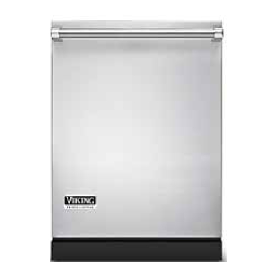
Viking FDWU324 Service Manual
Hide thumbs Also See for FDWU324:

Advertisement

Quick Links

Service
Manual
This manual is to be used by qualified appliance technicians only. Viking
does not assume any responsibility for property damage or personal
injury for improper service procedures done by an unqualified person.
Viking
Dishwasher
VIKING RANGE,
LLC
This Base Manual covers general and
specific information including, but not
limited to the following models:
Model #
FDWU/VDWU324
FDWU/VDWU524
FDWU/VDWU524W
SMK-0013
NOV 2018

Advertisement

Table of Contents
loading

Summary of Contents for Viking FDWU324

  • Page 1 Service VIKING RANGE, Manual This manual is to be used by qualified appliance technicians only. Viking does not assume any responsibility for property damage or personal injury for improper service procedures done by an unqualified person. Viking This Base Manual covers general and...
  • Page 2: Table Of Contents

    Table of Contents Table of Contents......2 Water Counter Fault E:15 ........37 Drain Pump Blocked Fault E:16 ......37 Important Information ....3 Auto Detergent motor positioning Fault E:17 ..38 SAVE THESE INSTRUCTIONS ....... 3 Wiring Diagrams ......39 Safety Information ............
  • Page 3: Important Information

    IMMEDIATE HAZARDS WHICH WILL RESULT IN SEVERE PERSONAL INJURY OR DEATH. CAUTION WARNING VIKING will not be responsible for any injury or property damage from improper service procedures. Hazards or unsafe practices which COULD result in If performing service on your own product, you must severe personal injury or death.
  • Page 4: Warnings

    Important Information Warnings Tip Over Hazard WARNING Read and follow all instructions before using Most of the unit’s weight this appliance to prevent the potential risk of is at the top. Extra care is TIP OVER HAZARD fire, electric shock, personal injury, or damage needed when moving the to the appliance as a result of improper usage Appliance is top heavy and tips easily when not...
  • Page 5: General Information

    General Information V D W U 5 2 4 W S Model Numbers V = Viking WS = With Salt Version D = Dish W = Washer U = Under counter Serial Numbers 0 4 1 0 1 8 D 1 0 0 0 0 2 3 4...
  • Page 6: E8 Control

    General Information E8 Control Program Menu Start / Menu Selection Selection Pause PADs On/Off Option Display Time De- PADs See next lay / Menu page Naviga- tion PAD Page 6 of 41 December 12, 2018...
  • Page 7: Display

    3 in 1 Tablet Icon models) Self cleaning filter (Not on Viking Liquid Detergent Icon (Not on models) Viking models) Ionizer (Not on Viking models) No Water Icon (Not on Viking models) 7 Segment Display Salt Indicator (Water softener models ) Delay Icon...
  • Page 8: Wash Cycles

    General Information AUTO CONDITION DESCRIPTION Drain 35 Seconds Fill 1.16 Gallons Circulation 6 minutes Circulation / Turbidity 90 Seconds Circulation / Heater up to 100.4°F Circulation / Turbidity 90 Seconds Circulation 3 Minutes PREWASH Circulation / Turbidity 90 Seconds Circulation / Heater / Detergent 60 seconds up to 122°F Circulation / Heater...
  • Page 9: Combi-Clean Cycle

    General Information COMBI CLEAN CONDITION DESCRIPTION Drain 35 Seconds Fill 1.16 Gallons Circulation 1 minute Circulation / Heater up to 107.6°F PRE WASH Circulation 6 minutes Circulation / Drain 15 Seconds Drain 45 Seconds Fill 1 Gallon Circulation 10 Seconds Circulation / Heater / Detergent 60 seconds Circulation / Heater...
  • Page 10: Pots Pan Cycle

    General Information POTS & PANS+ CONDITION DESCRIPTION Drain 35 Seconds Fill 1.16 Gallons Idle 10 Seconds Circulation / Heater up to 120°F PREWASH Circulation 5 minutes Circulation / Drain 15 Seconds Drain 45 Seconds Fill 1.11 Gallons Circulation 10 Seconds Circulation / Heater / Detergent 60 seconds Circulation / Heater...
  • Page 11: Regular Wash Cycle

    General Information REGULAR WASH CONDITION DESCRIPTION Drain 35 Seconds Fill 1.06 Gallons Circulation 6 Minutes Circulation / Turbidity 90 Seconds Circulation / Heater up to 100.4°F Circulation / Turbidity 90 Seconds Circulation 3 Minutes WASH Circulation / Turbidity 90 Seconds Circulation / Heater / Detergent 1 Minute up to 122°F...
  • Page 12: Glass Care Cycle

    General Information GLASS CARE CONDITION DESCRIPTION Drain 35 Seconds Fill 1.06 Gallons Circulation 10 Seconds Circulation / Heater / Detergent 60 Seconds PREWASH Circulation / Heater up to 113°F Circulation 12 Minutes Circulation / Drain 15 Seconds Drain 45 Seconds Fill .79 Gallons Circulation...
  • Page 13: Hour Wash Cycle

    General Information HOUR WASH CONDITION DESCRIPTION Drain 35 Seconds Fill 1.06 Gallons Circulation 10 Seconds WASH Circulation / Heater / Detergent 60 Seconds Circulation / Heater up to 120.2°F Circulation / Drain 15 Seconds Drain 45 Seconds Fill .85 Gallons Circulation 3 Minute RINSE...
  • Page 14: Quick Wash Cycle

    General Information QUICK WASH CONDITION DESCRIPTION Drain 35 Seconds Fill 1.16 Gallons Circulation 10 Seconds Circulation / Heater / Detergent 60 Seconds WASH Circulation / Heater up to 113°F Circulation 5 Minutes Circulation / Drain 15 Seconds Drain 45 Seconds Fill 1 Gallon Circulation...
  • Page 15: Rinse & Hold Cycle

    General Information QUICK WASH CONDITION DESCRIPTION Drain 35 Seconds Fill 1.11 Gallons RINSE & HOLD Circulation 11 Minutes Circulation / Drain 15 Seconds Drain 45 Seconds December 12, 2018 Page 15 of 41...
  • Page 16: Estimated Wash Times For Cycles

    General Information ESTIMATED WASH TIMES OPTIONS SELECTIONS OPTION COMBINATION DEFAULT Intense Express Intense Wash / High Express Function / PROGRAM Wash Function High Gloss Sanitize Gloss High Gloss TIME Auto 2:32 3:31 2:59 2:47 4:41 Combi Clean 3:02 3:49 1:46 3:27 4:25 2:24...
  • Page 17: Setting Menu

    1 = 1 dose 2 = 2 3 = 3 4 = 4 on display doses doses doses Ionizer (not available on Icon illuminated Viking models) Liquid detergent Dosage Icon illuminated (not available on Viking models) December 12, 2018 Page 17 of 41...
  • Page 18 General Information Enter the Service Menu by pressing and holding the ON/OFF pad and the MENU pad simultaneously for three seconds. The Display will count down, “ 3...2...1”. When the entire display screen is illuminated , release both pads. After three seconds, all of the LED’s will illuminate as shown to the right.
  • Page 19 General Information This is an automated test used in the factory at the end of line, skip this test by pressing and releasing the Time delay + pad to advance to the next item. The display will change to IFt as shown below, this is another factory only test, skip it by pressing and releasing the Time delay + pad to advance to the next item.
  • Page 20 Press the time delay + tab to go to the next item on the settings menu which is micro-filter enable disable, the micro-filter icon illuminates in the display window, however this function is not applicable to Viking models, press the time delay + tab again to go to the next item in the settings menu, see below.
  • Page 21 General Information This setting is the Auto Tablet Detector function in the settings menu and results in the icon illuminating as shown above. Press the Select tab to change the current setting. 0 = OFF 1 = ON. Press the time delay + tab again to go to the next item in the settings menu, Sound level, see below.
  • Page 22 General Information Press the time delay + tab again to go to the next item in the settings menu, Regeneration level this will apply to WS (water softener) models only, see below. Press the Select tab to change the current setting. r1 = no regeneration r2 = every 27.74 gal- lons r3 = every 13.74 gallons (factory default) r4 = every 7.93 gallons r5 = every 2.38 gallons.
  • Page 23 This is the ionizer function, the icon for the ionizer illuminates, however this function, again is not available on the Viking built models. Press the time delay + tab again to go to the next item in the settings menu, see next page.
  • Page 24: Service Menu

    Service Procedures Service Menu Enter the Service Menu by pressing and holding the ON/OFF pad and the MENU pad simultaneously for three seconds. The Display will count down, “ 3...2...1”. When the entire display screen is illuminated , release both pads. After three seconds, all of the LED’s will illuminate as shown to the right.
  • Page 25 Service Procedures This is an automated test used in the factory at the end of line, skip this test by pressing and releasing the Time delay + pad to advance to the next item. The display will change to IFt as shown below, this is another factory only test, skip it by pressing and releasing the Time delay + pad to advance to the next item.
  • Page 26: Automated Service Test

    Service Procedures With the door open and “SFT” in the display, press and release the “Start / Pause Pad”, as shown below. Close the dishwasher door and the test will begin, takes approximately 15 minutes, at which time the “END OF CYCLE” icon will illuminate.
  • Page 27: Fault Codes

    Service Procedures Fault Codes CODE DESCRIPTION VIKING UNITS E:01 Overflow E:02 No Water Fault E:03 Heater Fault E:04 Turbidity Fault E:05 Wash Diverter Valve Fault E:06 NTC Fault E:07 Water Inlet Valve Fault E:08 Main Board Communication Fault E:09 Display Board Communication Fault E:10 U.I.
  • Page 28 Service Procedures If not initiating the automated service test, the next service menu item is Shown above when stepping to the next menu item. This is the “EEP” (Eprom reset function), which will restore all factory settings to all parameters. Press the Start/Pause pad to reset the Eprom, see below illustration.
  • Page 29 Service Procedures This will result in the software for the following being displayed in sequence: Main Board software version Display board software version Button board software version December 12, 2018 Page 29 of 41...
  • Page 30: Troubleshooting

    Troubleshooting Troubleshooting Procedures E8 Dishwashers are electronically controlled and some faulty conditions can be detected by the electronics. These errors are detect- ed not only in the functional test program but also during the washing cycles. The previously detected errors are kept in memory and shown in display.
  • Page 31: No Water E:02

    Troubleshooting No Water E:02 Incoming water to the machine is monitored via a water counter (flow meter) system. Water counter generates electronic pulses. During the “Water Inlet” step (for any program including functional test) if no pulses could be sensed by the electronics, No Water condition occurs.
  • Page 32: Diverter Valve Fault E:05

    Troubleshooting Turbidity fault E:04 Turbidity sensor is the component that measures the amount of dirt in the water. The machine uses this data for the steps of Auto Pro- gram (if applicable). If the proper data from the turbidity sensor cannot be received, Turbidity Sensor Error occurs. When the error occurs, the program default will continue the program as heavy dirt level.
  • Page 33: Water Inlet Valve Fault E:07

    Troubleshooting NTC fault E:06 At the Heating step, if NTC resistance is measured beyond the specified resistance values or if the NTC resistance is measured as open/short circuit, NTC fault occurs. When the fault is detected software skips the heating step and continues the program with the next step.
  • Page 34: Display Board Communication Fault E:09

    Troubleshooting Main Board Communication Fault E:08 During the normal machine working cycle, if communication between main electronic board and external electronic board is lost; this fault is encountered. Possible reasons: • Cable harness errors • Faulty socket installation • Faulty electronics •...
  • Page 35: User Interface Communication Fault E:10

    • User Interface board (U.I.) THE FOLLOWING FAULT CODES ARE NOT CURRENTLY APPLICA- BLE TO VIKING BUILT UNITS, HOWEVER THEY ARE BEING INCLUD- ED IN CASE THEY ARE DISPLAYED ERRONEOUSLY OR IN THE EVENT THAT FUTURE CHANGES INCORPORATE THE FUNCTIONS THEY APPLY TO.
  • Page 36: Conducto Probe/Short Circuit Faults E:11 / E:12

    Troubleshooting Conducto Probe/Short Circuit Faults E:11 / E:12 These errors are encountered when conducto probe cable harness occurs or cable sockets installed in wrong direction. Possible reasons: • Cable harness errors • Faulty socket installation Pressure Switch Fault E:13 Machines with pressure switch feature, in washing cycle, after water inlet is completed the pressure switch is clicked. If it is not, pres- sure switch fault is encountered.
  • Page 37: Water Counter Fault E:15

    Troubleshooting Water Counter Fault E:15 At washing cycle water inlet step, if water counter does not increase but the pressure switch closes, the main board software encoun- ters E:15 fault. Possible reasons: • Cable between main board and water counter may be broken •...
  • Page 38: Auto Detergent Motor Positioning Fault E:17

    Troubleshooting Auto Detergent motor positioning Fault E:17 At liquid detergent dosing step, dosage motor tries to find right position. If position can not be found in specified time interval, position fault counter is increased. After 2 unsuccessful tries, electronic board gives E:17 error. Possible reasons: •...
  • Page 39: Wiring Diagrams

    Wiring Diagrams Control Panel Diagram BLDC Signal Kir Sensörü & NTC 3WVS YENI MESE ANA KART KN 5 KN 5 KN 8 KN 6 MAIN BOARD KN 11 KN 2 KN 4 KN 3 KN 10 KN 1 but-1 but-2 HEATER SOFT SOFT...
  • Page 40: Main Board Diagram

    Wiring Diagrams Main Board Diagram Page 40 of 41 December 12, 2018...
  • Page 41: Appendix

    Appendix December 12, 2018 Page 41 of 41...

This manual is also suitable for:

Vdwu324Fdwu524Vdwu524Fdwu524wVdwu524w

Table of Contents