Table of Contents
Advertisement
Quick Links
This document is provided with the DRV8886 customer evaluation module (EVM) as a supplement to the
DRV8886 datasheet
guide details the hardware implementation of the EVM.
1
...................................................................................................................
2
2.1
2.2
2.3
2.4
2.5
2.6
2.7
1
2
3
4
5
6
7
8
9
10
11
12
13
14
15
...................................................................................................................
16
1
Trademarks
MSP430 is a trademark of Texas Instruments.
Windows is a registered trademark of Microsoft Corporation.
All other trademarks are the property of their respective owners.
SLVUB15 - February 2017
Submit Documentation Feedback
DRV8886 Evaluation Module User's Guide
(DRV8886 2-A Stepper Motor Driver With Integrated Current
..............................................................................................................
..........................................................................................................
...........................................................................................................
..............................................................................................................
.......................................................................................................
..............................................................................................
................................................................................................
................................................................................................................
.........................................................................................
.................................................................................................
.........................................................................................................
..........................................................................................................
..............................................................................................................
............................................................................................
.........................................................................................................
........................................................................................................
.........................................................................................................
.......................................................................................
...............................................................................................
.............................................................................................................
Copyright © 2017, Texas Instruments Incorporated
Contents
........................................................................
List of Figures
................................................
......................................................
List of Tables
..............................................................
DRV8886 Evaluation Module User's Guide
User's Guide
SLVUB15 - February 2017
Sense). This user's
........................................
2
2
2
3
4
4
4
7
9
10
2
3
4
5
6
7
8
9
10
11
11
12
12
13
13
14
3
1
Advertisement
Table of Contents

Subscribe to Our Youtube Channel
Related Manuals for Texas Instruments DRV8886


Summary of Contents for Texas Instruments DRV8886
-
Page 1: Table Of Contents
User's Guide SLVUB15 – February 2017 DRV8886 Evaluation Module User's Guide This document is provided with the DRV8886 customer evaluation module (EVM) as a supplement to the DRV8886 datasheet (DRV8886 2-A Stepper Motor Driver With Integrated Current Sense). This user's guide details the hardware implementation of the EVM. -
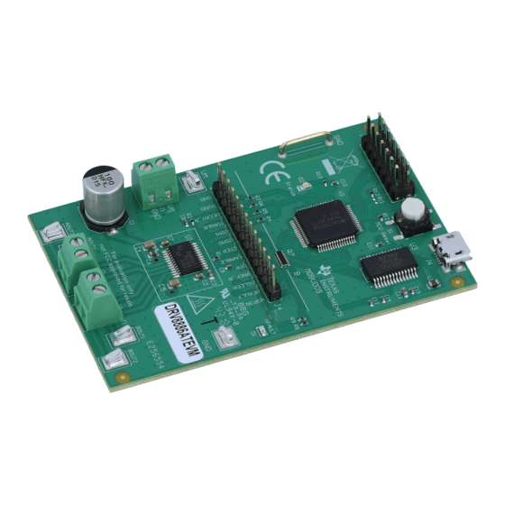
Page 2: Board Overview
Connectors The DRV8886 EVM offers access to the VM (motor voltage) power rail through a terminal block (J1). A set of test clips in parallel with the terminal block allows for the monitoring of the input power rail. -
Page 3: Test Points
Table 1 describes the connections available on the J4 header. Each header pin is labeled on the evaluation module, and connects to a similarly named pin of the DRV8886. Table 1. Connections to DRV8886 Using External Microcontroller Header Label Description V3P3R 3.3 V after 0 Ω... -
Page 4: Jumpers
EVM, the status LED will begin to blink. Step 5. Open the GUI. The GUI can be found in the start menu at Texas Instruments → DRV8886_EVM → DRV8886_EVM X.Y.Z, where X, Y, and Z are the revision numbers. If a shortcut was created, double-click on the shortcut to open the GUI. -
Page 5: Wake And Enable Toggle Buttons
The number 1.232 is based on the maximum current allowed using the configuration. If VRREF = 0 V, the maximum current is 1 A. The 12-bit DAC channel 1 is connected to the DRV8886 analog input RREF through a 15-kΩ series resistor. The DAC voltage begins at 1.232 V (0%) and ends at 0 V (100%). -
Page 6: Reciprocate Toggle Button
When selected, the STEP commands are stopped and the motor control buttons are disabled. To re-enable motor control, set the WAKE and ENABLE toggle buttons to green. DRV8886 Evaluation Module User's Guide SLVUB15 – February 2017 Submit Documentation Feedback... -
Page 7: Motion Control Frame (Includes Start/Stop Steps And Move Steps)
If the starting speed is greater than or equal to the target speed, the acceleration rate is set to 0. This setting will prevent further speed changes until the motor is stopped, and new starting and target speeds are entered. Texas Instruments recommends setting the starting speed to ½ the target speed to avoid this scenario. -
Page 8: Acceleration Profile
Stopping Speed parameter is often good enough to ensure good motion quality and application performance. Figure 8 shows the three conditions possible when stopping and the action taken. DRV8886 Evaluation Module User's Guide SLVUB15 – February 2017 Submit Documentation Feedback Copyright © 2017, Texas Instruments Incorporated... -
Page 9: Evm Documentation
DRV8886 EVM Hardware Files. The GUI, USB drivers, and MSP430F2617 source code are provided in the DRV8886EVM Firmware and GUI software file. SLVUB15 – February 2017 DRV8886 Evaluation Module User's Guide Submit Documentation Feedback Copyright © 2017, Texas Instruments Incorporated... -
Page 10: Appendix A Driver And Gui Installation Instructions
CDM v2.10.00 WHQL Certified.exe file and click the Yes button in the pop-up window. 2. Installing the GUI NOTE: The DRV8886 EVM GUI is designed to control both the DRV8886 EVM and the DRV8886AT EVM. The GUI automatically identifies the device and changes the pulldown menus as needed. -
Page 11: Evm Setup Wizard
Click the I accept the agreement radio button and click the Next button to continue (see Figure 11). Figure 11. License Agreement SLVUB15 – February 2017 Driver and GUI Installation Instructions Submit Documentation Feedback Copyright © 2017, Texas Instruments Incorporated... -
Page 12: Installation Folders
Download from web radio button and click the Next button to continue (see Figure 13). Figure 13. GUI Composer Runtime Selection Driver and GUI Installation Instructions SLVUB15 – February 2017 Submit Documentation Feedback Copyright © 2017, Texas Instruments Incorporated... -
Page 13: Possible Upgrade Question
Yes button and then click the Next button to continue (see Figure 14). Figure 14. Possible Upgrade Question Click the Next button to continue (see Figure 15). Figure 15. Ready to Install SLVUB15 – February 2017 Driver and GUI Installation Instructions Submit Documentation Feedback Copyright © 2017, Texas Instruments Incorporated... -
Page 14: Completed
Click the check box next to the desired results and then click the Finish button to complete the setup wizard (see Figure 16). Figure 16. Completed Driver and GUI Installation Instructions SLVUB15 – February 2017 Submit Documentation Feedback Copyright © 2017, Texas Instruments Incorporated... - Page 15 STANDARD TERMS FOR EVALUATION MODULES Delivery: TI delivers TI evaluation boards, kits, or modules, including any accompanying demonstration software, components, and/or documentation which may be provided together or separately (collectively, an “EVM” or “EVMs”) to the User (“User”) in accordance with the terms set forth herein.
- Page 16 FCC Interference Statement for Class B EVM devices NOTE: This equipment has been tested and found to comply with the limits for a Class B digital device, pursuant to part 15 of the FCC Rules. These limits are designed to provide reasonable protection against harmful interference in a residential installation.
- Page 17 【無線電波を送信する製品の開発キットをお使いになる際の注意事項】 開発キットの中には技術基準適合証明を受けて いないものがあります。 技術適合証明を受けていないもののご使用に際しては、電波法遵守のため、以下のいずれかの 措置を取っていただく必要がありますのでご注意ください。 1. 電波法施行規則第6条第1項第1号に基づく平成18年3月28日総務省告示第173号で定められた電波暗室等の試験設備でご使用 いただく。 2. 実験局の免許を取得後ご使用いただく。 3. 技術基準適合証明を取得後ご使用いただく。 なお、本製品は、上記の「ご使用にあたっての注意」を譲渡先、移転先に通知しない限り、譲渡、移転できないものとします。 上記を遵守頂けない場合は、電波法の罰則が適用される可能性があることをご留意ください。 日本テキサス・イ ンスツルメンツ株式会社 東京都新宿区西新宿6丁目24番1号 西新宿三井ビル 3.3.3 Notice for EVMs for Power Line Communication: Please see http://www.tij.co.jp/lsds/ti_ja/general/eStore/notice_02.page 電力線搬送波通信についての開発キットをお使いになる際の注意事項については、次のところをご覧ください。http:/ /www.tij.co.jp/lsds/ti_ja/general/eStore/notice_02.page 3.4 European Union 3.4.1 For EVMs subject to EU Directive 2014/30/EU (Electromagnetic Compatibility Directive): This is a class A product intended for use in environments other than domestic environments that are connected to a low-voltage power-supply network that supplies buildings used for domestic purposes.
- Page 18 Notwithstanding the foregoing, any judgment may be enforced in any United States or foreign court, and TI may seek injunctive relief in any United States or foreign court. Mailing Address: Texas Instruments, Post Office Box 655303, Dallas, Texas 75265 Copyright © 2017, Texas Instruments Incorporated...
- Page 19 IMPORTANT NOTICE FOR TI DESIGN INFORMATION AND RESOURCES Texas Instruments Incorporated (‘TI”) technical, application or other design advice, services or information, including, but not limited to, reference designs and materials relating to evaluation modules, (collectively, “TI Resources”) are intended to assist designers who are developing applications that incorporate TI products;...
Need help?
Do you have a question about the DRV8886 and is the answer not in the manual?
Questions and answers