
Related Manuals for CommScope FLX-PON


Summary of Contents for CommScope FLX-PON
- Page 1 Installation Instructions TC-1572-IP Rev A, February 2023 www.commscope.com COMMSCOPE FLX-PON NODE MOUNT CABINET COMMSCOPE FLX-PON 660105992 Page 1 of 29 Rev. A © 2023 CommScope, Inc. All Rights Reserved...
- Page 2 Do not drill or punch any holes in the cabinet. Use only the provided knockouts in the cabinet for cable ingress and cable egress. Drilling or punching holes in any other location will immediately void the warranty. No exemptions. 1 Registered trademark of the National Fire Protection Association. Page 2 of 29 © 2023 CommScope, Inc. All Rights Reserved...
-
Page 3: Table Of Contents
Overview and Specifications.....................................4 Reference Documents and Manuals .............................................4 Cabinet Weights (approximate) .............................................4 CommScope FLX-PON Cabinet Rack Unit (RU) Configurations ..................................4 Field Replacement Units (FRU) and Aftermarket Kits (AMK) ...................................4 Cabinet Views .....................................................5 Door View Examples with Thermosiphon and Air Conditioner Units ................................6 Door Clearances ..................................................7... -
Page 4: Overview And Specifications
Overview and Specifications This guide provides instruction on how to install a CommScope FLX-PON cabinet onto a concrete pad, or below grade vault and battery installation. Common Features • All cabinets have same mounting footprint - Figure 17 & 22 •... -
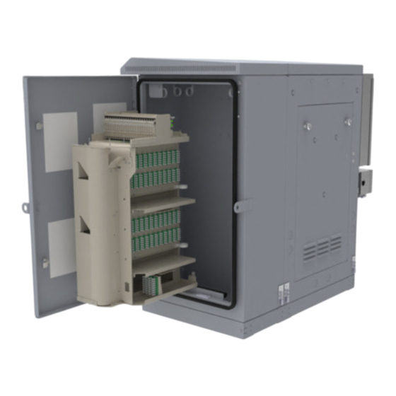
Page 5: Cabinet Views
Cabinet Views 41” (1041 mm) 46.5” (1182 mm) Figure 1. Front Views – COMMSCOPE FLX-PON Example 27.4” (696 mm) 34.6” (878 mm) Figure 2. Left, Rear, and Right Views – COMMSCOPE FLX-PON Example Sliders for Thermosiphon nodes Power supply drawer... -
Page 6: Door View Examples With Thermosiphon And Air Conditioner Units
All units have a DC power input and alarm output terminal block and RJ45 ports. Door with Air Conditioner: DC Power (D1-D7) A COMMSCOPE FLX-PON cabinet may utilize a DC unit per cabinet configuration and operating requirements defined by customer, Table A. -
Page 7: Door Clearances
Figure 6. COMMSCOPE FLX-PON Door Examples with Thermosiphon Units T1 per Table A Door Clearances Note: Figure 7 shows AC load center on cabinet right side to clarify door clearances. Optional AC load center can be mounted per customer request on either side. However, AC load center should not be installed on the left side for wall / H-frame mounting. -
Page 8: Rear Panel Removal And Installation
Only remove the packaging and pallet at the installation site. • Properly strap cabinet to a truck or trailer to prevent shifting, and always transport and store cabinet in an upright position. Page 8 of 29 © 2023 CommScope, Inc. All Rights Reserved... -
Page 9: Before Starting Installation
This section provides general installation considerations, unpacking and inspection procedures, and lists the tools and materials required for cabinet installation. Installation Overview: Installation of COMMSCOPE FLX-PON cabinet involves the following main tasks: 2.2.1 Installing a Support Base: The cabinet must be mounted on a suitable support base. The following two mounting options are available: •... -
Page 10: Unpacking And Inspection
Open the cabinet doors (requires 216B key tool) and check for missing ship-along parts (see installation drawing included with cabinet) or broken parts. If there are damages, contact CommScope for an RMA (Return Material Authorization) and to reorder if replacement is required. -
Page 11: Cabinet Mounting
39.54” (1004 mm) Rear Pad gasket Gasket (template) Cutout Front = Pallet bolt and anchor hole locations on cabinet floor Figure 13. Gasket (Template) Required Between Cabinet and Pad or Vault Page 11 of 29 © 2023 CommScope, Inc. All Rights Reserved... -
Page 12: Place Cabinet Onto Concrete Pad Or Steel Structure
16, Figure 17 and Figure 24. Alternate Mounting on a Steel Frame The Pad Mount Frame (MID; 760255236 | KIT,FLX-PON,FRAME,AIO), shown in Figure 16, is a stainless-steel frame that provides a mounting base for the cabinet when embedded in a concrete foundation. - Page 13 When installed, the top of the conduit should be located 1 to 2 inches (2.54 to 5.08 cm) below the top of the finished concrete pad. • Install the conduit before pouring the pad. Figure 17. Example of Cabinet Installation with 4-Inch Plinth on a Concrete Pad Page 13 of 29 © 2023 CommScope, Inc. All Rights Reserved...
- Page 14 When installed, the top of the rod should be located 1 to 2 inches (2.54 to 5.08 cm) below the top of the finished concrete pad. Leave sufficient slack in the grounding wire to allow it to be routed into the cabinet after the cabinet is mounted on the pad. Page 14 of 29 © 2023 CommScope, Inc. All Rights Reserved...
- Page 15 Feed the stubbed feeder and distribution cables into the appropriate conduit sections and route to the splice enclosure (not provided). Note: A separate splice enclosure (not provided) is required for splicing the cabinet OSP feeder and distribution cables to the network cables. Page 15 of 29 © 2023 CommScope, Inc. All Rights Reserved...
-
Page 16: Fasten Cabinet To Concrete Pad Or Vault
Fasten Cabinet to Concrete Pad or Vault Fasten cabinet to a concrete pad or vault from cabinet pad mount holes per Figure 13 and Figure 21. CommScope requires use of eight mounting holes. -
Page 17: Route And Connect Cables
Use door key to open and remove rear panel for cable access, Figure 8. • Use knockouts on cabinet topside only for stacking two cabinets (COMMSCOPE FLX-PON only), Figure 24. Figure 24. Cabinet Knockout Locations, COMMSCOPE FLX-PON Mounting The Cabinet On A Vault, or Fiberglass Sleeve The FMS is a fiberglass and polymer concrete sleeve that may be used to support the cabinet at ground level. - Page 18 There must be room for 12 inches (30.5 cm) of fill below and on each side of the FMS. The excavation dimensions for the large FMS are shown in Figure 26. Excavate a rectangular hole for the FMS. Figure 26. Excavation Recommendations for (FMS-FD3J-KIT-A) Page 18 of 29 © 2023 CommScope, Inc. All Rights Reserved...
- Page 19 Note: Label or tag the stub end of each cable so it can be identified after it is routed to the splice enclosure. Page 19 of 29 © 2023 CommScope, Inc. All Rights Reserved...
-
Page 20: Connect Cabinet To Main Earth Ground
Unpack the optical nodes that have been designated for installation into the cabinet. Retain all hardware, cabling, and documentation for later use. • Remove the front security bolts holding the sliding drawer(s) in place. Figure 28. Figure 28. Page 20 of 29 © 2023 CommScope, Inc. All Rights Reserved... - Page 21 Lift the node onto the node drawer while guiding the bolts through the slotted holes on the mounting tabs. Using a ½” socket, tighten the node mounting bolts to node manufacturer specification. Page 21 of 29 © 2023 CommScope, Inc. All Rights Reserved...
- Page 22 • Unpack the fiber cable flexible tube assembly and route all fiber patch cords through the node optical port. (The port location may vary depending on manufacturer). Figure 34. Page 22 of 29 © 2023 CommScope, Inc. All Rights Reserved...
- Page 23 Route coaxial cables from the power inserter AC ports to each node installed in the Flex-PON cabinet. (Node AC port locations may vary by manufacturer). Figure 36. • Close the cover on the node housing and tighten each of the housing bolts to manufacturer’s specification. Figure 37. Page 23 of 29 © 2023 CommScope, Inc. All Rights Reserved...
-
Page 24: Connect Cabinet To Main Power Source, Turn-Up
230 VAC and 120 VAC single-phase power feeds. • For all cabinet power connections and feeds, refer to the cabinet schematic drawing (SD) and equipment instruction manuals supplied with the cabinet. Page 24 of 29 © 2023 CommScope, Inc. All Rights Reserved... -
Page 25: Cabinet Battery Installation
Follow all battery and cabling instructions to reduce risk of fire, electric shock, and injury. Important Safety Precautions: • For only one battery string, CommScope recommends loading battery shelf #1 first. • The customer shall incorporate a containment system within the battery compartment of the cabinet to capture electrolyte in the case of a flooded battery. -
Page 26: Required Tools
Apply battery dimensions as required toward use of battery tray design in the CMC cabinet. 7RU or 8RU Battery Tray Spacing Options – Battery Recommendations COMMSCOPE FLX-PON Equipment and Battery Cabinets (mixed) – 7RU or 8RU Spacing Options • 7RU Battery Recommendations: —... -
Page 27: Battery Installation
Have the SD on hand to look at for battery and thermal probe connection details. • If installing batteries in a battery only cabinet also follow instruction on routing and connection to a COMMSCOPE FLX- PON power cabinet using battery interconnect kit 860651309 in the next section Installation - Battery Interconnect Kit - CMC. - Page 28 Locate battery cable marked BATT-. Remove protective lug cover and connect it to negative (-48V) terminal of left-most battery per Figure 43 or Figure 44. Figure 43. Battery String Cable Connection, Example Using Anderson Connectors Page 28 of 29 © 2023 CommScope, Inc. All Rights Reserved...
-
Page 29: Disclaimer
This product may be covered by one or more U.S. patents or their foreign equivalents. For patents, see www.cs-pat.com. This document is not intended to modify or supplement any specifications or warranties relating to CommScope products or services.
Need help?
Do you have a question about the FLX-PON and is the answer not in the manual?
Questions and answers