Advertisement

Quick Links

TC-96302-IP
Rev A, February 2021
commscope.com
Content
1
INTRODUCTION . . . . . . . . . . . . . . . . . . . . . . . . . . . . . . . . . . . . . . . . . . . . . . . . . . . . . . . . . . . . . . . . . . . . . . . . . . . . . . . . . . . . 2
1.1
EPX G2 Panel Configurations Covered by This User Manual . . . . . . . . . . . . . . . . . . . . . . . . . . . . . . . . . . . . . . . . . 2
1.2
EPX LGX/1000 Configurations Covered by This User Manual. . . . . . . . . . . . . . . . . . . . . . . . . . . . . . . . . . . . . . . . . 3
1.3
Available Accessories . . . . . . . . . . . . . . . . . . . . . . . . . . . . . . . . . . . . . . . . . . . . . . . . . . . . . . . . . . . . . . . . . . . . . . . . . 3
1.4
Parts List. . . . . . . . . . . . . . . . . . . . . . . . . . . . . . . . . . . . . . . . . . . . . . . . . . . . . . . . . . . . . . . . . . . . . . . . . . . . . . . . . . . . 4
1.5
Important Safety Cautions . . . . . . . . . . . . . . . . . . . . . . . . . . . . . . . . . . . . . . . . . . . . . . . . . . . . . . . . . . . . . . . . . . . . . 4
1.6
Precautions. . . . . . . . . . . . . . . . . . . . . . . . . . . . . . . . . . . . . . . . . . . . . . . . . . . . . . . . . . . . . . . . . . . . . . . . . . . . . . . . . . 5
1.7
Related Publications . . . . . . . . . . . . . . . . . . . . . . . . . . . . . . . . . . . . . . . . . . . . . . . . . . . . . . . . . . . . . . . . . . . . . . . . . . 5
2
PRODUCT DESCRIPTION . . . . . . . . . . . . . . . . . . . . . . . . . . . . . . . . . . . . . . . . . . . . . . . . . . . . . . . . . . . . . . . . . . . . . . . . . . . . 6
2.1
General Description . . . . . . . . . . . . . . . . . . . . . . . . . . . . . . . . . . . . . . . . . . . . . . . . . . . . . . . . . . . . . . . . . . . . . . . . . . . 6
2.2
EPX Panel as Shipped . . . . . . . . . . . . . . . . . . . . . . . . . . . . . . . . . . . . . . . . . . . . . . . . . . . . . . . . . . . . . . . . . . . . . . . . . 6
2.3
Main Product Features . . . . . . . . . . . . . . . . . . . . . . . . . . . . . . . . . . . . . . . . . . . . . . . . . . . . . . . . . . . . . . . . . . . . . . . . 7
2.4
Cable Gland Feature . . . . . . . . . . . . . . . . . . . . . . . . . . . . . . . . . . . . . . . . . . . . . . . . . . . . . . . . . . . . . . . . . . . . . . . . . . 8
2.5
Specifications and Dimensions . . . . . . . . . . . . . . . . . . . . . . . . . . . . . . . . . . . . . . . . . . . . . . . . . . . . . . . . . . . . . . . . . 9
3
UNPACKING AND INSPECTION . . . . . . . . . . . . . . . . . . . . . . . . . . . . . . . . . . . . . . . . . . . . . . . . . . . . . . . . . . . . . . . . . . . . . . .11
4
OVERVIEW OF INSTALLATION . . . . . . . . . . . . . . . . . . . . . . . . . . . . . . . . . . . . . . . . . . . . . . . . . . . . . . . . . . . . . . . . . . . . . . . 12
5
INSTALLING THE PANEL . . . . . . . . . . . . . . . . . . . . . . . . . . . . . . . . . . . . . . . . . . . . . . . . . . . . . . . . . . . . . . . . . . . . . . . . . . . . 12
5.1
Determining Rack Size and Mounting Hardware . . . . . . . . . . . . . . . . . . . . . . . . . . . . . . . . . . . . . . . . . . . . . . . . . . 12
Electronic Only Document (EOD)
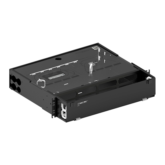
EPX Panel
Figure 1. EPX Panel (2U Shown)
User
Manual
73780-A
Page
Continued
© 2021 CommScope, Inc.

Advertisement

Table of Contents
loading
Need help?

Need help?

Do you have a question about the EPX G2 and is the answer not in the manual?

Questions and answers

Summary of Contents for CommScope EPX G2

  • Page 1: Table Of Contents

    EPX G2 Panel Configurations Covered by This User Manual ....... .
  • Page 2: Introduction

    CONTACT INFORMATION................26 1 INTRODUCTION The CommScope EPX Fiber Panel line is a flexible solution which allows interchangeable MPO modules, adapter packs, and splice cassettes, including in-panel splicing using splice trays. It is available in G2 or LGX/1000 bulkheads in 1U, 2U, and 4U sizes, sliding or fixed.
  • Page 3: Epx Lgx/1000 Configurations Covered By This User Manual

    760122903 BAF-3/4-NPT Bracket for Armor Fitting, 3/4 NPT 760122911 BAF-1-NPT Bracket for Armor Fitting, 1 NPT 760122929 BAF-1-1/4-NPT Bracket for Armor Fitting, 1-1/4 NPT 760122937 BAF-1-1/2-NPT Bracket for Armor Fitting, 1-1/2 NPT Page 3 © 2021 CommScope. All Rights Reserved.
  • Page 4: Parts List

    • Wearing safety glasses during installation of this panel is recommended. Although standard safety glasses provide no protection from potential optical radiation, they offer protection from accidental airborne hardware and cleaning solvents Page 4 © 2021 CommScope. All Rights Reserved.
  • Page 5: Precautions

    • Care should be taken not to compromise the stability of the rack by installation of this equipment. 1.7 Related Publications The following publication is available by contacting the CommScope Support Center at https://www.commscope.com/SupportCenter Title Number EPX Panel Quick Start...
  • Page 6: Product Description

    MPO MODULES, OR SPLICE CASSETTES SPLICE TRAY LOCATION CABLE ENTRY (EITHER SIDE) MOUNTING BRACKET (2X) HINGED FRONT SLIDING TRAY (OPTIONAL) COVER (SHOWN AT SECOND OPEN POSITION) 23401-A Figure 2. EPX 1U Panel as Shipped Page 6 © 2021 CommScope. All Rights Reserved.
  • Page 7: Main Product Features

    ACCOMMODATES ADAPTER PACKS, MPO MODULES, OR SPLICE CASSETTES CABLE ENTRY PORTS (EITHER SIDE) MOUNTING BRACKET (2) SLIDING HINGED REMOVABLE TRAY FRONT COVER (OPTIONAL) COVER LATCH 23381-A Figure 3. EPX panel (2U Shown) Page 7 © 2021 CommScope. All Rights Reserved.
  • Page 8: Cable Gland Feature

    Cables can also be secured with tie wraps and the lances provided in the back of the panel. 27392-A Figure 4. Direct Connection of Fiber Cables Using Fiber Glands Page 8 © 2021 CommScope. All Rights Reserved.
  • Page 9: Specifications And Dimensions

    19.0 IN. (48.26 CM) 1.72 IN. 12.91 IN. (32.79 CM) (4.36 CM) 12.61 IN. (32.03 CM) 1RU PANEL (FRONT VIEW) 12.42 IN. (31.54 CM) Figure 6. Dimensions of EPX Open Fixed Panel Page 9 © 2021 CommScope. All Rights Reserved.
  • Page 10 6.97 in (17.70 cm) Width 19.0 in. (48.26 cm) 19.0 in. (48.26 cm) 19.0 in. (48.26 cm) Depth 16.52 in. (41.96 cm) 16.52 in. (41.96 cm) 16.52 in. (41.96 cm) Side ports Page 10 © 2021 CommScope. All Rights Reserved.
  • Page 11: Unpacking And Inspection

    Inspect the exterior of the shipping container(s) for evidence of rough handling that may have damaged the components in the container. Unpack each container while carefully checking the contents for damage. If damage is found or parts are missing, contact the CommScope Support Center using the URL: http://www.commscope.com/SupportCenter Save any damaged cartons for inspection by the carrier.
  • Page 12: Overview Of Installation

    3/8-inch conversion screws included in accessory kit. Shelf will not be centered when mounted in rack. Mount panel to rack using four M6 x 12mm screws (provided as part of basic panel). Page 12 © 2021 CommScope. All Rights Reserved.
  • Page 13: Mounting Panel On Rack

    Set the panel into position on the screws just installed. Secure the panel to the rack by installing the remaining two mounting screws. 27418-A Figure 8. Mounting the EPX Panel (1U Panel Shown) Page 13 © 2021 CommScope. All Rights Reserved.
  • Page 14: Opening The Front Door

    To open the front door: (a) move the door latch inward and (B) open the door allowing it to hang down until flat with the frame. Refer to Figure 27382-A Figure 9. Opening the Front Door Page 14 © 2021 CommScope. All Rights Reserved.
  • Page 15: Operating The Sliding Tray (If Panel Has Sliding Tray)

    To release a closed drawer, press the release button down, as shown in Figure 10 (c), and slide the drawer out to the first detent (d). 27383-A Figure 10. Releasing Closed Drawer to Open It Page 15 © 2021 CommScope. All Rights Reserved.
  • Page 16: Installing Adapter Packs

    Align the adapter pack with the selected location in the bulkhead. Push in and secure with push in pin if present (LGX/1000 only). Refer to Figure 11 Figure 27411-A Figure 11. Installing Adapter Packs (G2) SECURE WITH PUSH PIN 27396-A Figure 12. Installing Adapter Packs (LGX/1000) Page 16 © 2021 CommScope. All Rights Reserved.
  • Page 17: Installing Mpo Modules

    1. Align the MPO module with the selected location in the bulkhead. Push in and secure with push in pin if present (LGX/1000 only). Refer to Figure 13 Figure 27412-A Figure 13. Installing MPO Modules (G2) 27397-A SECURE WITH PUSH PIN 27397-A Figure 14. Installing MPO Modules (LSX/1000) Page 17 © 2021 CommScope. All Rights Reserved.
  • Page 18 27393-A Figure 15. Installing Cable Gland (Standard 1/2-inch Cable Gland, Provided) 3. Loop the MPO cable around through the cable retainers as shown in Figure Figure 16. Cable Routing to MPO Modules Page 18 © 2021 CommScope. All Rights Reserved.
  • Page 19: Installing Splice Cassettes

    2. Route cables from rear of panel to splice cassettes as shown in Figure 18 below. Figure 18. Cable Routing to Splice Modules (G2 shown) 3. Splice fibers from cable to splice cassette per instructions included with the splice cassettes. Page 19 © 2021 CommScope. All Rights Reserved.
  • Page 20: Installing Agile Splice Trays

    Refer to the instructions enclosed with that kit for all details not covered here. Up to two splice trays may be installed per U height. 1. Install the splice tray as shown in Figure 27398-A Figure 19. Installing Splice Trays Page 20 © 2021 CommScope. All Rights Reserved.
  • Page 21 On 2U and 4U shelves splice trays may be installed stacked on top of each other. Note: Ensure that suitable slack is provided to allow tray on sliding versions to fully extend Figure 20. Cable Routing to AGILE Splice Tray (G2 shown) Page 21 © 2021 CommScope. All Rights Reserved.
  • Page 22: Field Termination

    3. Terminate connector end of pigtails into module adapter openings in standard sequence. 4. Spool excess fiber slack length. 5. Repeat items 1-4 for all remaining locations. Figure 21. Cable Routing in EPX Panel Page 22 © 2021 CommScope. All Rights Reserved.
  • Page 23: Cable Routing

    All of these standard cable glands have the same basic components and are installed in the same way, as shown in Figure 27393-A Figure 22. Installing Standard Cable Gland (1/2-inch Gland in EPX 1U Panel Shown) Page 23 © 2021 CommScope. All Rights Reserved.
  • Page 24 1U panels include snap-fit washers to reduce the 1/2-inch opening to 3/8-inch, as shown in Figure 27416-A Figure 23. Installing 3/8-inch Cable Gland With Snap-Fit Washers (EPX 1U Panel Only) For additional information on smaller diameter cables, refer to Section 2.4 on page Page 24 © 2021 CommScope. All Rights Reserved.
  • Page 25: Installing A Cable

    6. Feed fibers and subunit tubes through panel opening. Temporarily coil fibers loosely in panel. 7. Insert threaded body of cable gland into opening and tighten gland nut onto threaded section to secure cable gland unit to panel. Page 25 © 2021 CommScope. All Rights Reserved.
  • Page 26: Contact Information

    TC-96302-IP 7 CONTACT INFORMATION • To find out more about CommScope ® products, visit us on the web at www.commscope.com • For technical assistance, customer service, or to report any missing/damaged parts, visit us at http://www.commscope.com/SupportCent Page 26 © 2021 CommScope. All Rights Reserved.

Table of Contents