Table of Contents
Advertisement
Quick Links
TC-1069-IP
Rev A, Mar 2017
www.commscope.com
Contents
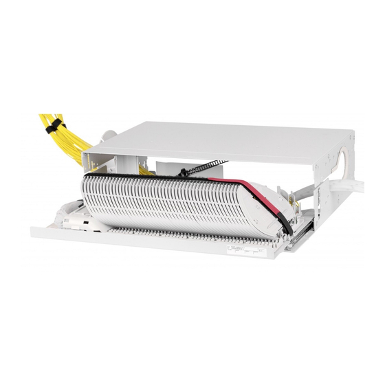
Fist Generic Splicing Shelf
1 Introduction
c
IFC
1 Introduction
Product function
•
The Generic Splicing Shelf is a multi-purpose mechanical shelf assembly for the FIST fiber management system
in a rack environment.
•
The product is typically used :
-
to store splices of external cable to external/indoor cable
-
to store splices of external cable to pigtails.
-
to store splices of pigtails to pigtails
•
It can be installed in Tyco's FIST Racks and other 19" or metric (ETSI) rack sizes.
•
Accessories are available for termination of most common cable types.
•
Modular wraparound groove plates can be clicked in the UMS (Universal Mounting System) profile. They
provide the foundation for mounting combinations of SOSA2 (Splicing Only Sub-Assembly) and/or SASA2
(Splitter Array Sub-Assembly) modules. Typically, Single Circuit or ribbon fiber management is used.
•
Kevlar Termination Units (KTU's) can be mounted in the shelf to provide the necessary strain relief when
terminating common pigtail types.
•
The shelf is delivered with a metal hingable cover.
FIST-GSS2 / FIST-GSS3
I N S T A L L A T I O N
shelf using cable termination plate
a
Loose tube cable
4.3 Back cable termination directly on
the shelf using cable termination
plate
a
Loose tube
6.1
6.2
I N S T R U C T I O N
Advertisement
Table of Contents

Related Manuals for CommScope FIST-GSS2


Summary of Contents for CommScope FIST-GSS2
-
Page 1: Table Of Contents
FIST-GSS2 / FIST-GSS3 I N S T A L L A T I O N I N S T R U C T I O N TC-1069-IP Rev A, Mar 2017 Fist Generic Splicing Shelf www.commscope.com 4.2 Side cable termination directly on the... -
Page 2: General
General Installation of the shelf Kit content 3.1 Mounting the shelf in the rack Kit content: example: FIST-GSS2-MA Install the mounting brackets on the correct position. • 1 shelf, incorporating GR mounting is shown. Metal chassis with drawer Hingable and removable front cover... - Page 3 3.1.4 Mount the shelf using the FACC-ALLEN-KEY. 3.1.5 If necessary mount the adaptation brackets 19”-ETSI (FIST-MB2-M or FIST-MB2-M-AS). 3.1.3 If a non-Tyco rack is being used it is possible that the cage nuts may not fit. In this case use locally supplied ones and install in accordance with local practices.
-
Page 4: Preparation Of The Shelf
Preparation of the shelf Preparation of the trays 3.3.1 Pull the drawer to the fully open position. Remove the Velcro and the FAS block cover by lifting the back side of the cover. a) Cable to pigtail 3.2.1 Install the trumpet by positioning it centrally in the opening at the side of the shelf, align the small knobs with the slots in the side, Strongly push and turn until the locking pin clicks into positioning hole. - Page 5 3.3.6 If necessary, the groove plates can be removed using 2 flat screwdrivers. 3.3.4 Click the groove plates on the aluminum profiles starting from the FAS block; don’t leave any gaps. First position the pins of the groove plate at the back and pull the groove plate to the front until it locks.
-
Page 6: Cable To Cable
b) Cable to cable 3.3.11 If necessary, trays can be removed using the fiber guiding pin. 3.3.8 In case of a pure cable-cable configuration: no KTU-brackets are placed, the groove plates are not modified, tubes enter at both Cable termination sides of the FAS block. - Page 7 4.1.8 Bring the flex tube into the flex tube holder. 4.1.4 In case 2 flex tubes will be used: remove the releasable tie- wrap and mount the plastic stand-off in the first hole from the front. 4.1.9 Mount the fixed tie wrap at the position as shown. 4.1.5 Prepare a piece of flex tube going from the cable termination plate in the rack to the flex tube holder on the shelf.
- Page 8 4.1.12 Strip the loose tubes from the mark and cut the overlength of the transportation tubes. Clean the fibers very well to make feeding easier. 4.1.15 Pull the fibers at the other end of the tubes. 4.1.16 If no more loose tubes have to be terminated, cut the unused tubes.
- Page 9 b) Central core (single fiber or ribbon) and loose tube ribbon FIST-GR-CTB100CC (central core) Breakout device Breakout device cover + screws Cable bracket + screws Mounting bracket + washers + screws 2 cable clamps Unraveling tool 2 strength member stops + screws 4.1.18 Choose a position in the side duct or on the cable termination plate as close as possible to the GSS.
-
Page 10: Central Core Cable
4.1.22 Central core cable 4.1.26 In case of ribbon cable Remove twists in the ribbons. a) If ribbons are according ITU norms: use the unraveling device. The numbers indicate the number of ribbons you want to bundle (3-4-5 or 6). 3 sizes of ribbon can be handled: ribbon 12, 8 and 4. - Page 11 IFC cable 4.1.29 Insert the tubes in the connectors. Use 6 positions at the left 4.1.32 Kit content FIST-ITK2 when cable is mounted at the left side of the bracket. • 1 pc IFC-bracket • 2 pcs bolts & nuts •...
-
Page 12: Side Cable Termination Directly On The
4.1.35 Apply one layer of foam tape around the IF-cable, at the end of the jacket. This tape prevents easy pull-out of the cable. 4.1.39 In case of single circuit tray (SC): 2 fibers can be terminated. The following positions should be used on the metal bracket: 1, 2, 4, 5, 7, 8, 10, 11. - Page 13 70 mm 4.2.5 In case of front mounting, mount the fixed tie wrap as shown. 4.2.2 Right side mounting cable coming from the top. 4.2.6 Mark the transportation tubes 10 mm from the plastic stand-off. Mark the loose tubes 30 mm from the plastic stand-off. 4.2.3 Strip the cable over 3,5 m.
- Page 14 4.2.8 The FOPT-CT should overlap loose tube and transportation tube. 4.2.10 In case of max. 4 cables, use the FIST-UST-EXKIT-2CA for the next 2 cables. 4.2.11 An extra plate can be used with a limitation of 2 cables on top of each other (positions as shown).
-
Page 15: Modular Cable
Modular cable 4.2.16 Secure the transportation tubes on the stand off brackets in two 4.2.13 Assemble the releasable tie wraps and the strength member bundles as shown in the picture. connectors onto the side termination plate as shown in the picture. 4.2.17 Remove the outer cable jacket over a distance of 3500 mm starting from the side term plate and cut the strength member at 65 mm from the cable jacket. - Page 16 4.3.2 In case of strength member termination in the rack (use FIST-GSS2-CT-BR-2): mount the flex tube holder and the plastic stand-off n case of 19” and ETSI. In case of 15” there is no stand-off needed. Mount the tubes to the black stand-off with a tie wrap. Protect 4.2.22 Insert the fibers and loose tube(s) into the FOPT-CS.
-
Page 17: Termination Of The Pigtails
4.3.4 In case of strength member termination on the shelf (use FIST-GSS2-CT-BS-2): mount the cable plate, the strength member connectors, the black stand-off and the tie-wraps as shown in 4.3.6. Use the plastic spacers between plate and shelf. The distance between the plate and the right side of the shelf X is 8 cm for a 19”... - Page 18 In case of 2 pigtails In case of 2 pigtails/KTU; identify 1 of the fibers with a marking pen. Guide the prepared pigtail in the KTU. Make sure the kevlar yarns do not entangle the fibers. Guide the prepared pigtails in the KTU. Make sure the kevlar yarns do not entangle the fibers.
- Page 19 In case of 4 pigtails Diameter of the pigtails maximum 1.8 mm 5.13 Close the KTU. 5.11 Installation of first and second pigtail at the same side of the KTU. 5.14 Pull the jacket and Kevlar at the same time to slide the inner part of the KTU into the outer part.
- Page 20 5.17 If the pigtail diameter > 2.6 mm, use the fiber guiding pin to push the pigtail into the pigtail slot. 5.18 Guide the fibers into the corresponding groove. Make sure all fibers are positioned under the lips. 5.16 Slide the KTU in the correct slot. Respect correct orientation of the KTU.
-
Page 21: Splicing + Storage
6.1.2 Guide the fibers in the groove plate. Make sure all fibers are positioned under the lips. Splice the fibers and protect the splice. Position the splice in the spliceholder. 5.19 Make sure the transition of secondary to primary coating is in the splice protector. -
Page 22: Ribbon
Closing the shelf 6.1.4 If both fibers are coming from the same side, follow the routing as shown. Tray 1 is closest to fiber routing block Side 2 of tray Side 1 of tray Cable port N° from Cable port N° from fibers entering tray... -
Page 23: Important Steps
Close the drawer by activating the spring on the right side of the unit. Close the cover. 8 Important steps • Clean the fibers very well to make feeding easier. • Always respect 30mm bendradius and prevent kinking when repositioning tie-wraps for the transportation tubes. •... - Page 24 © 2017 CommScope, Inc. All rights reserved. web at www.commscope.com All trademarks identified by ® or ™ are registered trademarks or trademarks, respectively, of CommScope, Inc. For technical assistance, customer service, or to report any This document is for planning purposes only and is not intended to modify or supplement any specifications or warranties relating to missing/damaged parts, visit us at: CommScope products or services.
Need help?
Do you have a question about the FIST-GSS2 and is the answer not in the manual?
Questions and answers