
Related Manuals for Zepro ZS MK2


Summary of Contents for Zepro ZS MK2
- Page 1 Technical Manual ZS MK2 ZEPRO Tel.: +46 (0)10-459 05 00 Email: zeprotech@hiab.com zepro.com 79872TL 2023-09-06...
-
Page 3: Table Of Contents
Control card ....................10 TLC B1 relay card ..................10 Functional descriptions and schematics ............. 16 ZS MK2 ...................... 16 ZS MK2 with digital auto tilt ..............25 Troubleshooting ..................36 Causes of malfunctions ................36 Troubleshooting strategy ................. 36... -
Page 4: Product Overview
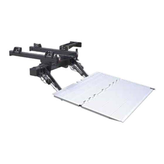
There should also be a sticker showing the same information in the users manual and on the door sill on the drivers side of the vehicle. For the ZS MK2 models covered in this document, the following nomenclature is used. The "ZS" denotes the model designation followed by the "Mk2" which denotes second generation design of the ZS product. "SLI"... - Page 5 1.1.2 Main components All ZS MK2 variants consist of the same main components shown below. The support frame contains the hydraulic unit and the control system and serves as the main attachment point for the lift arm and the cylin- ders, two of which are used to lift and the other two to tilt the platform.
- Page 6 Whether the tail lift is equipped with auto tilt or not can- not be detrmined by reading the typesign. Instead, the platform should be checked for sensors. If there's a rectangular angle sensor installed, then the tail lift is equipped with auto tilt. Fig 2. Rectangular angle sensor. www.zepro.com...
- Page 7 The control card receives inputs from the control device and the sensors and converts them into outputs to the solenoid and magnets which produce in the desired moton. All ZS MK2 variants are equipped with the TLC-B1 control card based on solid state relay technology. The card is used in other Zepro tail lifts as well and has a few different configurations depending on which tail lift it is meant to control. It is therefore crucial to always make sure that the configuration of the installed card is correct, especially when replacing the card.
-
Page 8: Accessing The Card And Hydraulic Unit
With the cover removed, the hydraulic unit is accessed by swinging the card out of the way, disconnecting the quick connector for the cable harness, removing the securing nut for the hydraulic unit tray and sliding the tray out. www.zepro.com... -
Page 9: Battery And Cable Requirements
Some vehicle models have restrictions regarding the amount of current the lift can access from the existing battery. Some vehicle models do not fully charge the battery. It may therefore be necessary to switch to a battery and sometimes also to a charger with a larger capacity. www.zepro.com... -
Page 10: Control Card
Control card Control card TLC B1 relay card 2.1.1 Overview The TLC B1 control card can be split into different functional sections as shown in the following figure. In- depth explanations of each section are contained in the following chapters. Fig 4. TLC B1 control card www.zepro.com... - Page 11 The Zepro solution consists of a cab switch, which when active, sends power to the CS pin in the cab switch section of the card. When the switch is in its "Off" position any inputs are disregarded and the tail lift is efec- tively locked.
- Page 12 Fig 7. Supply socket for different sensors The TLC B1 card can accomodate the sensor types shown in the table below. Different variants of the ZS MK2 use different types and number of sensors depending on functionality. See the functional descriptions and schematics chapter for connection information.
- Page 13 The control devices can be grouped into two groups depending on their functionality: primary and secondary devices. Primary devices are fixed on the outside of the box body or on the tail lift itself and can operate all functions of the tail lift without any limitations. The most common primary control devices for the ZS MK2 are shown below. Fig 8. CD 20 Fig 9. CD 3...
- Page 14 Secondary devices on the other hand, are usually accessible from the platform and are in some cases mobile. Therefore, they have certain limitations for safety or practical reasons and cannot operate all functions of the tail lift. The most common secondary control devices for the ZS MK2 are shown below. Fig 10. CD 9 Fig 11.
- Page 15 To the left of the output block there is a LED strip with 10 LED’s used for active output indication. The bottom LED lights up when the control card is powered. It should stay lit constantly during normal operation. The top 9 LED’s are used to indicate active output with each output having its own dedicated LED. www.zepro.com...
-
Page 16: Functional Descriptions And Schematics
ZS MK2 3.1.1 Description A ZS MK2 variant with double acting tilt cylinders, single acting lift cylinders and no auto tilt functionality. Sensor inputs: S3 - The S3 sensor input is bridged to the S3+ sensor power output. S4 - Pressure sensor located on the positive hydraulic feed to the left lift cylinder used to activate the open platfom alarm. - Page 17 Functional descriptions and schematics ZS MK2 Function: slide out Description: Slide out from transport to working position. Control input: Out. Available on primary control devices only. Sensor input: None apart from bridged S3. High pressure Return flow Active Card indication: Must be active for the function to be executed.
- Page 18 Functional descriptions and schematics ZS MK2 Function: lower Description: Vertical platform lowering. Control input: Down. Available on all control devices. Sensor input: None apart from bridged S3. High pressure Return flow Active Card indication: Must be active for the function to be executed.
- Page 19 Functional descriptions and schematics ZS MK2 Function: tilt down Description: Platform tilt down. Control input: Down + Tilt. Available on all control devices. Sensor input: None apart from bridged S3. High pressure Return flow Active Card indication: Must be active for the function to be executed.
- Page 20 Functional descriptions and schematics ZS MK2 Function: tilt up Description: Platform tilt up. Control input: Up + Tilt. Available on all control devices. Sensor input: None apart from bridged S3. High pressure Return flow Active Card indication: Must be active for the function to be executed.
- Page 21 Functional descriptions and schematics ZS MK2 Function: raise Description: Vertical platform raising. Control input: Up. Available on all control devices. Sensor input: None apart from bridged S3. High pressure Return flow Active Card indication: Must be active for the function to be executed.
- Page 22 Functional descriptions and schematics ZS MK2 Function: slide in Description: Slide in from working to transport position. Control input: In. Available on primary control units only. Sensor input: None apart from bridged S3. High pressure Return flow Active Card indication: Must be active for the function to be executed.
- Page 23 Functional descriptions and schematics 3.1.2 Summary of active valves ZS MK2 Safety Safety Motor Valve Valve Valve Slide out Slide in Valve lift, Valve lift, Soleonid Slide out Lower Tilt Down Tilt up Raise Slide in www.zepro.com...
- Page 24 Functional descriptions and schematics 3.1.3 Schematic ZS TLC-B1 www.zepro.com...
-
Page 25: Zs Mk2 With Digital Auto Tilt
ZS MK2 with digital auto tilt 3.2.1 Description A ZS MK2 variant with double acting tilt cylinders, single acting lift cylinders and digital auto tilt functionality. Sensor inputs in use: S1 - The S1 sensor input is bridged to the S1+ sensor power output. - Page 26 Functional descriptions and schematics ZS MK2 with digital auto tilt Function: slide out Description: Slide out from transport to working position. Control input: Out. Available on primary control devices only. Sensor input: None apart from bridged S3. High pressure Return flow...
- Page 27 Functional descriptions and schematics ZS MK2 with digital auto tilt Function: lower Description: Vertical platform lowering. Control input: Down. Available on all control devices. Sensor input: None apart from bridged S3. High pressure Return flow Active Card indication: Must be active for the function to be executed.
- Page 28 Functional descriptions and schematics ZS MK2 with digital auto tilt Function: auto tilt down Description: Automatic tilting down once ground level has been reached. Control input: Down. Available on all control devices. Sensor input: Active S5 pressure sensor, bridged S1 and S3.
- Page 29 Functional descriptions and schematics ZS MK2 with digital auto tilt Function: manual tilt down Description: Platform tilting down from horizontal. Control input: Down + Tilt. Available on all control devices. Sensor input: None apart from bridged S3. High pressure Return flow...
- Page 30 Functional descriptions and schematics ZS MK2 with digital auto tilt Function: manual tilt up Description: Platform tilting up from horizontal. Control input: Up + Tilt. Available on all control devices. Sensor input: None apart from bridged S3. High pressure Return flow...
- Page 31 Functional descriptions and schematics ZS MK2 with digital auto tilt Function: auto tilt up Description: Automatic tilting up until platform is horisontal. Control input: Up. Available on all control devices. Sensor input: Active S2 angle sensor, bridged S3. High pressure...
- Page 32 Functional descriptions and schematics ZS MK2 with digital auto tilt Function: raise Description: Vertical paltform raising. Control input: Up. Available on all control devices. Sensor input: None apart from bridged S3. High pressure Return flow Active Card indication: Must be active for the function to be executed.
- Page 33 Functional descriptions and schematics ZS MK2 with digital auto tilt Function: slide in Description: Slide in from transport to working position. Control input: In. Available on primary control units only. Sensor input: None apart from bridged S3. High pressure Return flow...
- Page 34 Functional descriptions and schematics 3.2.2 Summary of active valves ZS MK2 Safety Safety Motor Valve Valve Valve Slide out Slide in Valve lift, Valve lift, Soleonid Slide out Lower Auto tilt Down Tilt Down Tilt up Auto tilt Raise Slide in...
- Page 35 Functional descriptions and schematics 3.2.3 Schematic ZS MK2 with digital auto tilt www.zepro.com...
-
Page 36: Troubleshooting
"ON" position. If the tail lift is completely dead, use a multimeter to troubleshoot the power supply starting at the tail lift and moving towards the battery. Possible causes include but are not limited to a dead battery, a tripped fuse or disconnected or damaged power and/or ground cables. www.zepro.com... - Page 39 BUILT TO PERFORM Zepro, Del and Waltco are Hiab trade marks for tail lifts. Hiab is a world-leading supplier of equipment, intelligent services and digital solutions for on-road load handling. As an industry pioneer, our company commitment is to increase the efficiency...
Need help?
Do you have a question about the ZS MK2 and is the answer not in the manual?
Questions and answers