Advertisement
Quick Links
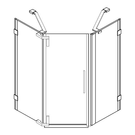
VIGO INDUSTRIES INSTALLATION GUIDE FOR
SHOWER ENCLOSURE (MODEL VG06064)
!
SAFETY PRECAUTIONS
This Installation Guide uses the following symbols to indicate important information.
Always observe the instructions indicated by these symbols.
!
WARNING
Instructions that, if ignored, could result in death or serious personal injury caused by
incorrect handling or installation of the product. These instructions must be observed for
safe installation.
!
CAUTION
The instructions for the following unit is based off of the Vigo brand shower base. The
instructions can not be provided for any other installation other than that of the Vigo brand.
The warranty will be voided if the following was not performed properly.
IMPORTANT
Maintenance and other important non-personal injury and non-material damage instructions
or statements that should be observed.
It is highly advised to dry fit the unit prior to any installation.
*VIGO reserves the right to modify/update all hardware and glass components based on
bettering the product for the end user's experience. If you have any questions contact VIGO
Tech Support at 1-866-591-7792.
1
Advertisement

Subscribe to Our Youtube Channel
Related Manuals for VIGO VG06064


Summary of Contents for VIGO VG06064
- Page 1 CAUTION The instructions for the following unit is based off of the Vigo brand shower base. The instructions can not be provided for any other installation other than that of the Vigo brand. The warranty will be voided if the following was not performed properly.
- Page 2 MODEL VG06064 ONTARIO INSTALLATION INSTRUCTIONS FOR SHOWER ENCLOSURE PLEASE READ INSTRUCTIONS BEFORE PROCEEDING Parts List 12. Plastic anchor green (2pc) 1. 1 5/8" Hex screw (6pc) 13. Threshold (1pc) 2. Plastic anchor white (6pc) 13B. Threshold end caps (2pc) 3. Glass support (4pc) 14.
- Page 3 17. 3/4" PHILLIPS SCREW 19. 8mm SCREW COVER 21. SUPPORT ASSEMBLY 22. SUPPORT ASSEMBLY (WITHOUT HINGE SLOTS) (HINGE SIDE) (NON HINGE SIDE) 98033 98111 98124 98123 97045CL36 97045CL42 18. SIDE GLASS PANEL 20. 4mm SCREW COVER CLIPS 98122 98040 MODEL VG06064...
- Page 4 36" 16 1/2" 25" 15 3/4"x74" 15 3/4"x74" 24 1/2"x72 7/8" 22" ** - GLASS AND HARDWARE WITH CORRESPONDING VIGO BRAND BASE VG06068 (FULLY INSTALLED) #14- DOOR (97044) DOOR OPENING #10- SIDE GLASS #16- SIDE GLASS DIM. "D" MODEL DIM. "A"...
-
Page 5: Before Starting
Compare items on your invoice with what you have received. Carefully review the Packing List on page 2. If any items are missing contact Vigo Industries at 1-866-591-7792. Please check our website at www.vigoindustries.com for additional information or instructional videos. - Page 6 Properly apply silicone to the wall and base joints. Make sure to read corresponding base instructions carefully prior to install on the Vigo Brand Shower Door System. Failure to do so can cause water leakage and bodily harm.
- Page 7 THE CABIN cause the shower to potentially leak and can cause potential fatal harm. SCREW (1) WALL INSIDE OF OUTSIDE OF SHOWER SHOWER HEX SCREW GLASS SIDE GLASS PANEL SUPPORT (3) GASKET VIEW FROM THE TOP MODEL VG06064...
- Page 8 Remove the side glass panel. Drill holes into respective marks and insert plastic anchors (#2) inside them. Not necessary if installing into studs. Studs are the preferred means of installation, anchors can pull out of the wall causing property damage and bodily harm. MODEL VG06064...
- Page 9 GASKETS hinge on the side glass panel as shown. Make sure the set screw side if facing the wall. Screw into place with the set screws through the support assembly (hinge side) (#21) with the allen key provided. MODEL VG06064...
-
Page 10: Installing The Door Panel
2. Part #5 is reversible and pre-cut on top LOOK INSIDE THE CABIN and bottom to fit in proper configuration. Cutting/finishing is needed but only after fully installing and only at the top of the unit. VIEW FROM THE TOP MODEL VG06064... - Page 11 The door magnetic seal strip (#8) is reversible. Do not install the handle first, this is dangerous and may cause the glass to break. MODEL VG06064...
- Page 12 GASKETS FACE completely tighten. Leave rather loose so they can slide on the glass panel. NOTE: 1. When the Vigo logo is facing out the face of the glass support (#3) will face out. OUTSIDE OF THE CABIN MODEL VG06064...
- Page 13 MAGNETIC SEAL STRIP CONNECTION WILL BE HELD HERE BY ONE PERSON DURING THIS ENTIRE STEP. SECOND PERSON SLIDES THE GLASS SUPPORTS ALONG THE GLASS UNTIL THEY MEET THE WALL. MODEL VG06064...
- Page 14 Loosen the bottom hinge inside plate and slide the glass until the magnetic seals are firmly locked. There is a total of 6mm horizontal adjustment. LOOSEN PLATE 6mm ADJUSTMENT SLIDE MODEL VG06064...
- Page 15 Note: There is a 6mm adjustment built into the mounting plate of the wall connector (#9). It is important to perform a dry fit prior to install. Once everything is level and plumb then you can begin your drilling. MODEL VG06064...
- Page 16 Studs are the preferred means of installation, anchors can pull out of the wall causing property damage and bodily harm. Untighten the plate from the wall connector (#9) and screw into the wall with a 1 5/8" screw (#1). PLATE MODEL VG06064...
- Page 17 I nstall the other structural arm (#6) into GASKETS the support assembly (#22) through the PLATE side glass panel (#16). Place gaskets on each side of the side glass panel (#16). Screw the plate into the structural arm. MODEL VG06064...
- Page 18 PLATE WITH A PENCIL plate. Note: There is a 6mm adjustment in the wall mount bracket plates. It is important to perform a dry fit prior to install. Once everything is level and plumb then you can begin your drilling. MODEL VG06064...
- Page 19 Studs are the preferred means of installation, anchors can pull out of the wall causing property damage and bodily harm. 10. Untighten the plate from the wall connector (#9) and screw into the wall with a 1 5/8" screw (#1). PLATE MODEL VG06064...
- Page 20 11. Replace the wall connector (#9) onto the plate. Replace the structural arm (#6). TIGHTEN HERE Tighten all set screws with the hex key supplied. MODEL VG06064...
-
Page 21: Installing The Handle Assembly
SET SCREW OUTSIDE HANDLE SET SCREW INSIDE HANDLE (BOTTOM) METAL WASHER METAL CLEAR WASHER WASHER CLEAR WASHER THREADED SCREW GLASS SUPPORT INSTALLING THE THRESHOLD Position the side glass panel clips (#18) to the side glass panels (#10 and #16). MODEL VG06064... - Page 22 Put the threshold (#13) into the threshold end caps (#13B). Place the threshold (#13) and threshold end caps (#13B) over the side glass panel clips (#18). Screw into the floor with 3/4" screws (#17). Screw into the floor with 3/4" phillips screws (#17). MODEL VG06064...
- Page 23 NOTE: If the seal strip is the diagram. not flat or twisted, use hot water and a hair dryer to apply minimal heat and press the seal strip back into position. OUTSIDE OF INSIDE OF THE CABIN THE CABIN MODEL VG06064...
-
Page 24: Installing Covers
(#10, #16) and threshold. Apply clear silicone caulk to the seal strip connections of the door bottom seal strip and the door magnetic seal strip. NOTE: Cut any excess overhang of seal strips at the top of the panels. MODEL VG06064... - Page 25 REGULAR CARE AND MAINTENANCE OF YOUR VIGO SHOWER ENCLOSURE Your home is a moving entity, shifting and settling over time. Vigo understands this and has designed their shower enclosures with this in mind. It is the responsibility of the homeowner or end user to maintain the integrity of their newly installed enclosure, using the integrated adjustability features.
Need help?
Do you have a question about the VG06064 and is the answer not in the manual?
Questions and answers