Table of Contents
Advertisement
Quick Links
REMOTE CONTROL
USER'S MANUAL
Thank you very much for your purchasing the REMOTE CONTROL for our
packaged air conditioner.
This user's manual describes cautions for safety. Please read this manual carefully before use in order to operate the unit properly.
Keep this manual, after reading, at a safe place where you can consult it whenever it is necessary.
When the ownership of the unit is changed, please be sure to transfer this manual and the "Installation Manual" to a new owner.
It is not recommended for a user to install or move the unit by the user's own discretion. (Safety or functions may not be assured.)
English is Original
RC-EX3D
PJZ012A232
202309
Advertisement
Table of Contents

Related Manuals for Mitsubishi Heavy Industries RC-EX3D


Summary of Contents for Mitsubishi Heavy Industries RC-EX3D
- Page 1 English is Original REMOTE CONTROL RC-EX3D USER'S MANUAL Thank you very much for your purchasing the REMOTE CONTROL for our packaged air conditioner. This user's manual describes cautions for safety. Please read this manual carefully before use in order to operate the unit properly.
-
Page 3: Table Of Contents
Contents 1. Before you use ……………………… 2 Safety precautions ………………………………………… 2 Precautions for waste disposal …………………………… 3 Unit specifications ………………………………………… 3 Names and functions of sections on the R/C …………… 4 Menu item …………………………………………………… 6 2. Menu items …………………………… 8 Run ……………………………………………………………... -
Page 4: Before You Use
1. Before you use Safety precautions ● Please read the precautions written here carefully to operate the unit properly. You are required to observe these fully because every item of these instructions is important for safety. Failure to follow these instructions may result in serious consequences WARNING such as death, severe injury, etc. -
Page 5: Precautions For Waste Disposal
Do not wash the remote control with water or liquid. It could cause electric shocks, fire or break-down. Do not touch electric parts or operate buttons or screens with wet hands. It could cause electric shocks, fire or break-down. Do not dispose the remote control by yourself. It could destruct the environment. -
Page 6: Names And Functions Of Sections On The R/C
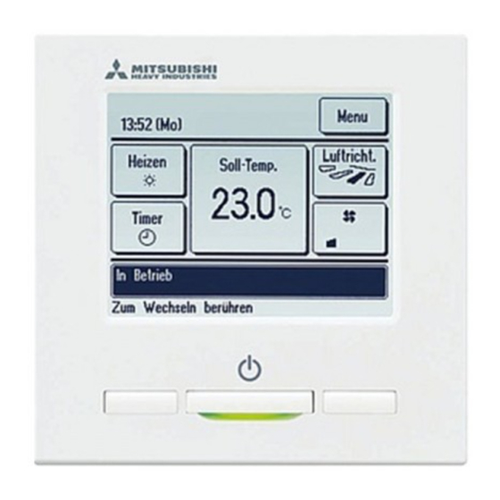
Names and functions of sections on the R/C (Operating section) 5 LCD (With backlight) 3 F2 switch 4 Operation lamp 6 USB port (mini-B) Run/Stop switch 2 F1 switch Touch panel system, which is operated by tapping the LCD screen with a finger, is employed for any operations other than the 1 Run/Stop, 2 F1 3 F2 switches. - Page 7 Names and functions of sections on the R/C (Display) ∗All icons are shown for the sake of explanation. 1 Clock, Room name display 2 Icon display TOP screen 3 Menu button 5 Change set temp button 4 Change operation 6 Change flap mode button direction button 8 Timer button...
-
Page 8: Menu Item
Menu item Main menu Basic operation Run ………………………………………………………………………………………… 8 Stop ………………………………………………………………………………………… 8 Change operation mode ………………………………………………………………… 9 Change set temp ………………………………………………………………………… 9 Change flap direction …………………………………………………………………… 10 Change the fan speed …………………………………………………………………… 13 F1, F2 switch operation …………………………………………………………………… 13 Anti draft ON/OFF operation …………………………………………………………… 14 High power operation ……………………………………………………………………... -
Page 9: Main Menu
Main menu Service setting Installation settings Installation date ………………………………………………………… 26 Company information …………………………………………………… 26 Test run …………………………………………………………………… 26 Static pressure adjustment ……………………………………………… 26 Change auto-address …………………………………………………… 26 Please refer to the Address setting of main IU ……………………………………………… 26 installation manual. IU back-up function ………………………………………………………... -
Page 10: Menu Items
2. Menu items Push the Run/Stop switch. Operation lamp (green) lights and operation starts. Stop Press the Run/Stop switch while the unit is in operation. The operation lamp turns off and the operation stops. When the operation stops, all operation buttons on the screen turn off. When the set lighting time of backlight ( ☞... -
Page 11: Change Operation Mode
Change operation mode Tap the Change operation mode button on the TOP screen. When the Change operation mode screen is displayed, tap the button of desired mode. Change operation mode The operation mode changes, and the display returns to the TOP Cooling screen. -
Page 12: Change Flap Direction
When the Change set temp screen is displayed, select the temperature as desired with using ▲ ▼ buttons. Change set temp After selecting the set temp, tap the button. The display Auto returns to the TOP screen. ■For allowable temperature setting ranges, refer to the range setting of set temp (☞page 57). - Page 13 When one or more FDKs with a left/right flap are connected, the Select flap screen is displayed. Select the desired flap direction. Select flap Left/right flap Upper/lower flap 1 To change the up/down flap direction, tap the Upper/lower flap button. The Change flap direction screen for the up/down flap is displayed.
- Page 14 ■ When multiple IUs are connected to the remote control for a mixed environment consisting of FDKs with a left/right flap and IUs without a left/right flap, enabling the 3D auto flow operation will set the models without a left/right flap to a flap position set before the 3D auto flow operation was started.
-
Page 15: Change The Fan Speed
Change the fan speed Tap the Change the fan speed button on the TOP screen. When the Change the fan speed screen is displayed, tap the button of desired fan speed. Change the fan speed After setting the fan speed, the display returns to the TOP screen. ■... -
Page 16: Anti Draft On/Off Operation
Anti draft ON/OFF operation (for using panel with anti draft) Anti draft can be turned ON/OFF (operated/stopped) with a single tap of the button. To turn ON/OFF the anti draft with the F1 or F2 switch, the anti draft ON/OFF function needs to be preset to the F1 or F2 switch. -
Page 17: High Power Operation
High power operation The high power operation adjusts the room temperature quickly to a pleasant level by increasing the operation capacity. The high power operation continues for 15 minutes at the maximum and returns to the normal operation automatically. When the operation mode is changed, the high power operation returns to the normal operation, too. High power operation must be set to the F1 or F2 switch ( ☞... -
Page 18: Energy-Saving Operation
Energy-saving operation Use this operation to save energy. Set temp is fixed at 28°C in the cooling operation or 22°C in the heating operation. Since the capacity is controlled automatically based on the outdoor temperature, energy can be saved without losing comfort. -
Page 19: Quick Reference Of Menu Items
3. Quick reference of menu items Quick reference of menu items It is necessary to input the Administrator password for menu items showing. Setting and display items Details Useful functions Individual flap control Set the moving range (upper and lower limit positions) of the flap at each blow outlet of IU. - Page 20 Setting and display items Details Filter Filter sign reset Reset the filter sign. page 76 Set next cleaning date. User setting Initial settings Clock setting Set and correct the current date and time. ■ When the power supply is interrupted for 80 hours or less, the clock continues to operate with the built-in backup page 36 batteries.
-
Page 21: Restrictions On The Sub R/C
Restrictions on the sub R/C When one IU is controlled with 2 R/Cs, the following settings cannot be made on the sub R/C. It is necessary to use the main R/C. In case of the sub R/C, the icon S is displayed on the R/C screen. ○: operable ×: not operable R/C operations Main... -
Page 22: Operations On Menu Screens
Operations on menu screens Tap the Menu button on the TOP screen. Main menu screen is displayed. When a desired menu item is tapped, setting screen for each item is displayed. When there are two or more pages, the Next button is displayed at the leading page and the Previous button is displayed at the last page. -
Page 23: Cautions For Each Setting Screen
When an item is referenced to Administrator password in this manual, the Input password screen is displayed after selecting the Input password menu. Input the administrator password. Enter the administrator password (4-digit number) and tap the Delete button. When the password is unknown or wrong, the setting cannot be changed. -
Page 24: Settings And Operations
4. Settings and operations Energy-saving setting [Administrator password] Tap the Menu button on the TOP screen and select Energy-saving setting Energy-saving setting . The Energy-saving setting menu Sleep timer screen is displayed. Peak-cut timer Automatic temp set back When the Energy-saving setting screen is displayed, select a desired Motion sensor control item. - Page 25 ■ Peak-cut timer Set the times to start and stop the capacity (upper limit) limiting operation and the peak-cut %. Advice · When the peak-cut timer is used, be sure to make the Clock setting in advance (☞page 36). · The peak-cut timer control may not be performed depending on combination of IU and OU. Tap the Menu button on the TOP screen and select...
- Page 26 Screen to check contents of current setting is displayed. When the contents are changed or new setting is added, select a 1 Peak-cut timer setting line No. and tap the 2 Change button. State Start time End time Enable 7:00 PM 8:00 PM Disable 7:00 AM...
- Page 27 Set the peak-cut %. Set the peak-cut % with the ▲ ▼ buttons. Peak-cut timer The peak-cut % can be set at 0%, 40%, 60% or 80%. Wed: No.1 The lower the peak-cut % is, the higher the effect of Peak-cut energy-saving becomes.
- Page 28 ■ Automatic temp set back It returns to the set temperature when the set time is counted up. Tap the Menu button on the TOP screen and select Automatic temp set back . The Energy-saving setting Automatic temp set back ⇒...
- Page 29 ■ Motion sensor control (for IUs with motion sensors) Presence of humans and the amount of motion are detected by a motion sensor to perform various controls. ■When the R/C is set as the sub R/C, the motion sensor control cannot be set. Tap the Menu button on the TOP screen and select Energy-saving setting ⇒...
- Page 30 Use the button to set the time, and tap the ▲ ▼ button. You can set the time between 1 to 50 hours in 1-hour intervals. Temporarily set the period required between the time when it continuously judges that there are no human after the "Operation wait"...
-
Page 31: Individual Flap Control
Individual flap control Motion range (upper, lower, left, or right limit positions) of the flap at each blow outlet can be set to a desired range. ■When the R/C is set as the sub R/C, the individual flap control cannot be set. Tap the Menu button on the TOP screen and select... - Page 32 Select the number of the flap of which the motion range is changed. ( ☞ 4) №② ■When there are two or more flaps at the blow outlet, such as the FDT type, the flap at blow outlet No. 1 will keep moving while the blow 制...
- Page 33 Select one of the lower limit positions from 1 to 6 for the flap Flap1 Swing range motion range. The range of motion between the upper and lower limit positions will be displayed in black. After you select the range, tap the button.
- Page 34 Select one of the right limit positions from 1 to 5 for the flap Flap2 Swing range motion range. The range of motion between the left and right limit positions will be displayed in black. After you select the range, tap the button.
-
Page 35: Anti Draft Setting
Anti draft setting (for using panel with anti draft) You can set ON/OFF (operation/stop) of the anti draft function and can also enable/disable the motion of panel with anti draft for each blow outlet for each operation mode. ■When the R/C is set as the sub R/C, the anti draft setting cannot be set. Tap the Menu button on the TOP screen and select... - Page 36 Select the blow outlet number to set anti draft. ■ The flap at blow outlet No. 1 will keep moving while the blow outlet selection screen is displayed. Select the flap based on this figure. When you have selected the blow outlet, the flap with the number you selected will move. The figure displayed on the screen shows the installed unit viewed from the floor side.
-
Page 37: Ventilation Operation
■ ON/OFF setting The indoor unit No. and the ON/OFF state of each anti draft function are displayed to allow ON/OFF setting of the anti draft. Anti draft is turned OFF by tapping ON and turned ON by tapping OFF. When two or more indoor units equipped with anti draft function are connected to the R/C, the two or more indoor units are displayed. -
Page 38: Initial Settings
Initial settings Tap the Menu button on the TOP screen and select User setting ⇒ Initial settings . When the “Initial settings” menu screen is displayed, tap a desired Initial settings item. Clock setting • Clock setting …… ☞ page 36 Date &... - Page 39 Set the “hour : minute” with the ▲ ▼ buttons on the clock setting screen. Clock setting Tap the button after the setting. To change “dd/mm/yy” tap the Date button. Date Back Set the time. ■ Date & time display You can set and correct the date &...
- Page 40 ■ Summer time You can adjust the current time by one hour. Tap the Menu button on the TOP screen and select User setting Initial settings ⇒ ⇒ Summer time . The Summer time setting screen is displayed. Changing from Disable to Enable … (Current time + 1 hr) is Summer time displayed.
- Page 41 ■ Backlight You can turn ON/OFF the backlight and set the lighting period. Tap the Menu button on the TOP screen and select User setting Initial settings ⇒ ⇒ Backlight . The Backlight setting screen is displayed. Tap the ON or OFF buttons for the backlight lighting and the lighting Backlight Period (5 - 90 sec, at 5-sec intervals).
-
Page 42: Timer
■ Operation lamp luminance You can adjust the operation lamp luminance. Tap the Menu button on the TOP screen and select User setting Initial settings ⇒ ⇒ Operation lamp luminance The Operation lamp luminance adjustment screen is displayed. You can adjust the luminance of the operation lamp to a desired Operation lamp luminance level by tapping the ▲... - Page 43 ■Operation of each timer • Sleep timer (☞page 22) Stops the operation of the unit when the amount of time set has elapsed since the start of the operation. When the setting is enabled, this timer will activate whenever any operation starts. •...
- Page 44 ■ Set ON timer by hour When the set time elapses, the air conditioner starts. Tap the Menu button on the TOP screen and select Useful functions ⇒ Timer ⇒ Set ON timer by hour . The Set ON timer by hour setting screen is displayed. Select desired hours for the period to start operation by timer with Set ON timer by hour ▲...
- Page 45 Select a desired temperature (at 1°C intervals) with the ▲ ▼ buttons. Or tap the Auto button and select the Set ON timer by hour auto temp setting. Auto Tap the button after the adjustment. ( ☞ 4) When the No setting button is tapped, “--°C” is displayed, and it starts operation at the last setting temperature.
- Page 46 ■ Set ON timer by clock Starts the operation of the unit at the set clock time. Tap the Menu button on the TOP screen and select Useful functions ⇒ Timer ⇒ Set ON timer by clock The Set OFF timer by hour setting screen is displayed. Select a desired time to start operation (5-min intervals) with the Set ON timer by clock ▲...
- Page 47 ■ Weekly timer You can set four on timer and off timer operations for each day of the week. Advice · The Clock setting (☞page 36) must be made when the weekly timer is used. · The weekly timer can be set from the main R/C only. Tap the Menu button on the TOP screen and select...
- Page 48 Screen to check contents of current setting is displayed. When the contents are changed or new setting is added, select a 1 Weekly timer Weekdays setting line No. and tap the 2 Change button. State Type Time Mode Fan Temp Enable 11:00 AM Enable...
- Page 49 Tap a desired operation mode. When the No setting button is tapped, it operates with the same Weekly timer operation mode at the last action. ( ☞ 7) Cooling Heating Auto No setting Back Please select operation mode. Select a desired temperature (at 1°C intervals) with the ▲...
- Page 50 Display the setting contents check screen. To register the setting, tap the Enter button. Weekly timer Weekdays (1) In case of group setting (2-1Weekdays, 2-2Sat/Sun, 2-3All State Type Time Mode Fan Temp days setting), move to the group setting screen. ( ☞ 13) Enable 11:00 AM Enable...
-
Page 51: Home Leave Mode
Home leave mode [Administrator password] Use this function to maintain the room temperature at a moderate level for avoiding extremely hot or cool after leaving home. ■Cooling and heating operations are controlled according to the outdoor air temperature. ■The set temperature and fan speed can be set. Advice ·... - Page 52 [To change the operation conditions] Tap the Menu button on the TOP screen and select Useful functions ⇒ Home leave mode ⇒ Details The Details setting menu is displayed. The following items can be Home leave mode set. Determine temp rule in cooling 1 Determine temp rule in cooling: Set the outdoor temperature to Determine temp rule in heating judge the operation mode in cooling.
- Page 53 Set the outdoor temperature for the “Determine temp rule in heating”. Select a desired set temp (0°C to 15°C, at 5°C intervals) with the Determine temp rule in heating ▲▼ ▲ ▼ buttons. to set offset value. Tap the button after the setting. Back Set the indoor temperature to start operation in cooling after setting the “Determine temp rule in cooling”.
-
Page 54: Registering Favorite Settings
Set the fan speed in heating mode. Tap a desired fan speed. Fan speed rule in heating Back Select the fan speed. After the settings of steps to 8, the display returns to the Details setting menu 1. Tap the Back button to return to the Home leave mode screen. To start operation, tap the Start button. Registering favorite settings Operation mode, set temp, fan speed, fan direction can be registered as Favorite set 1 and Favorite set 2. -
Page 55: Favorite Setting Operation
Favorite setting operation You can start an operation with the operation mode, set temp, fan speed, flap direction registered to Favorite set 1 and Favorite set 2. Settings for the operation mode, set temp, fan speed, flap direction can be registered from Favorite setting on the menu ( ☞... -
Page 56: Administrator Settings
Administrator settings [Administrator password] Tap the Menu button on the TOP screen and select User setting ⇒ Administrator settings The administrator password input screen is displayed. Enter the administrator password. When the administrator setting menu is displayed, tap a desired Administrator settings item. -
Page 57: Permission/Prohibition Setting
■ Permission/Prohibition setting Tap the Menu button on the TOP screen and select User setting ⇒ Administrator settings ⇒ Permission/Prohibition setting . The Permission/Prohibition setting menu is displayed. Following items can be selected, and the Permission or Prohibition Permission/Prohibition setting can be set for them. -
Page 58: Outdoor Unit Silent Mode Timer
Permission Prohibition for each item. Run/Stop Permission Prohibition Back Select the item. ■ Outdoor unit silent mode timer Set the period of time to operate the OU with prioritizing the quietness. When the Outdoor unit silent mode timer setting is Enabled, the silent mode operation starts and ends everyday at the same time until the setting is Disable. -
Page 59: Setting Temp Range
Set the start time for the Outdoor unit silent mode timer. Select a desired time (at 5-min intervals) with the ▲ ▼ Outdoor unit silent mode timer Start time buttons. If the Set button is tapped after setting the start time, the display changes to the end time setting screen. - Page 60 Set the range of setting temperature in the cooling operation. Menu Select at desired lower and upper limit temperatures (at 1°C Setting upper/lower limit temp in cooling intervals) with the ▲ ▼ buttons. Cool/Dry/Fan lower limit upper limit After Selecting the desired settings, tap the Set button. Back ▲▼...
-
Page 61: Temp Increment Setting
■ Temp increment setting Temperature increment for the change of the set temp can be changed. Tap the Menu button on the TOP screen and select User setting Administrator settings ⇒ ⇒ Temp increment setting The Temp increment setting screen is displayed. Tap a desired temperature increment. - Page 62 ■ R/C display setting Contents of display on the R/C can be changed. Tap the Menu button on the TOP screen and select User setting Administrator settings ⇒ ⇒ R/C display setting . The R/C display setting menu screen is displayed. R/C display setting 1 Room name …...
- Page 63 1 Room name Set the room name to be displayed on the TOP screen. Tap the Menu button on the TOP screen and select User setting Administrator settings ⇒ ⇒ R/C display setting Room name . ⇒ The Room name input screen is displayed. The room name can be set with up to 9 2-byte letters (18 1-byte letters).
- Page 64 When the letter selection screen is displayed same as at the setting of the name of R/C ( ☞ page 61), enter letters. The name of IU can be entered up to 4 2-byte (8 1-byte) letters. When the input is over, tap the button.
- Page 65 When R/C sensor setting is enabled, the room temperature (R/C) MEETING1 °C is displayed (refer to the installation manual on how to make Menu 16:00 (Mon) these settings). Direction Auto Set temp Timer Room(R/C) In operation for running. F1: High power F2: Energy-saving 4 Error code display Select ON/OFF for the Error code display.
- Page 66 6 Defrost operation display When frost on the OU heat exchanger is accumulated and the conditions for start defrosting are established, the defrost operation control is performed automatically. Select ON/OFF for the Defrost operation display. Tap the Menu button on the TOP screen and select User setting Administrator settings ⇒...
- Page 67 8 Display temp of R/C, Room, Outdoor Select ON/OFF for the display of the R/C sensor temperature, room temperature and outdoor temperature. Tap the Menu button on the TOP screen and select User setting Administrator settings ⇒ ⇒ R/C display setting Display temp of R/C, Room, Outdoor ⇒...
- Page 68 ■ F1/F2 function setting Use the F1 and F2 switches to change the functions to operate. Advice • When using a standard FDT/FDTC panel (a panel without anti draft function), set functions other than the Anti draft ON/OFF function to the F1 and F2 switches.
- Page 69 ■ Refrigerant leak detector setting Set the various settings related to the refrigerant leak detector. Tap the Menu button on the TOP screen and select User setting Administrator settings ⇒ ⇒ Refrigerant leak detector setting . Advice • The Refrigerant leak detector setting can be set from the main R/C only. •...
- Page 70 Set the LED brightness. 1 Normal ... 100% brightness. 2 Low 1 ... 75% brightness. 3 Low 2 ... 50% brightness. Set the threshold for refrigerant density alarm. 1 High ... The same level as the concentration when refrigerant leak is detected. 2 Normal ...
-
Page 71: Silent Mode Control
Silent mode control The OU is controlled with priority on quietness. You can start/stop the silent mode control. Menu [Starting control with button] Tap the Menu button on the TOP screen and select Useful functions Silent mode control ⇒ The administrator password input screen is displayed. Enter the administrator password. -
Page 72: Select The Language
Select the language Select the language to be displayed on the R/C. [Selecting the language with the button] Tap the button on the TOP screen while the air conditioner is stopped. ■Depending on how the Permission/Prohibition setting (☞page 55) is set, the administrator password input screen may be displayed. -
Page 73: Auto Anti Draft Ctl
Auto anti draft ctl You can set each blow outlet operation for auto anti draft ctl and can also enable/disable for allow to air flow volume ■When the R/C is set as the sub R/C, the auto anti draft ctl cannot be set. Tap the Menu button on the TOP screen and select... - Page 74 ■ Flap selection Select the blow outlet number to set auto anti draft ctl. ■ The flap at blow outlet No. 1 will keep moving while the blow outlet selection screen is displayed. Select the flap based on this figure. When you have selected the blow outlet, the flap with the number you selected will move.
-
Page 75: Note Wireless Interface Setting
Wireless interface setting Set the various settings related to the wireless interface. ■When the R/C is set as the sub R/C, the wireless interface setting cannot be set. Tap the Menu button on the TOP screen and select Useful functions ⇒... - Page 76 ■ After setting using the R/C, you need to set from the application "Smart M-Air". For information about how to install and operate "Smart M-Air", refer to the "WF-PAC-E" manuals on the MITSUBISHI HEAVY INDUSTRIES THERMAL SYSTEMS, LTD. website. HP: http://www.mhi-mth.co.jp/en/products/detail/ air-conditioner_users_manual.html...
-
Page 77: Control Mode & Eco Level
Control mode & Eco level Automatically controls the capacity depending on the R/C set temperature and the indoor temperature, which enables the energy-saving operation without sacrificing comfort. ■When the R/C is set as the sub R/C, the control mode & eco level cannot be set. Tap the Menu button on the TOP screen and select... -
Page 78: Filter Sign Reset
Filter sign reset In order to announce the time for cleaning of the air filter, the message of “Filter cleaning. Touch here.” is displayed when the cumulative operation time of the IU reaches the preset time. After you clean the filter, you must reset the operation time. Tap the message display on the TOP screen. -
Page 79: Maintenance Of Unit And Lcd
5. Maintenance of unit and LCD Maintenance of unit and LCD ■Wipe the surface of LCD and main body of the remote control with a dry cloth when cleaning is required. ■If the dirt on the surface cannot be removed, soak the cloth in neutral detergent diluted with water, squeeze the cloth tightly, and clean the surface. -
Page 80: Useful Information
6. Useful information Contact company & Error display If any error occurs on the air conditioner, the “Unit protection stop” is indicated on the message display. Take the following measures, stop the operation and consult your dealer. "Prot.stp.ON E Touch here for contact. History can be checked from Menu."... -
Page 81: Notice Of Inspection Date
7. Notice of inspection date If the next service date is set on the Service & Maintenance menu by your dealer, the following screen is displayed for 5 seconds at the start of operation and for 20 seconds from the end of operation on the beginning of the month which includes the set date. - Page 82 ■ “In operation for defrosting.” display When frost forms on the OU, the heating performance will decrease. Menu This will cause the unit to automatically switch to defrost operation, and 20:20 (Tue) hot air will stop blowing out from the IO. Direction Heating Set temp...
- Page 83 ■ “During condensation prevention control.” display If the humidity around the IU is high, the fan speed and flap direction may differ from the set fan speed and flap direction in order to prevent condensation forming on the IU, and the anti draft may close. In that case, the message "During condensation prevention control."...
- Page 84 ■ “Power control ON” display This is displayed in the message display area when power control of the motion sensor control ( ☞ page 27) is enabled and power control is executed. Also, the corrected temperature is displayed for Set temp by power control.
- Page 85 ■ “In temporary stop mode”, “In forced thermostat OFF”, “In setting temperature shift” displays These messages will be displayed when the unit is operated through IU Menu external input. 16:32 (Mon) This does not indicate a failure; the message indicates that the unit is Direction Cooling Set temp...
- Page 86 ■ “Periodical check” display (for equipment PAC) “Periodical check" may be displayed on the message display area when the total number of operation hours of the IU reaches the set time to notify you that it is time to replace the fan belt. If "Periodical check"...
- Page 87 ■ “Refrigerant is leaking. Ventilate room.” message display This message is displayed if the refrigerant sensor detects a refrigerant leak. Extinguish fire on combustion appliances, then ventilate the room. Please note that the IU fan may operate automatically. Call the phone number shown to inform us of the content of the message.
- Page 88 If you want to turn off the message, tap the message display area while the message is being displayed. The Refrigerant sensor sign reset screen is displayed. Tap the button. If you do not want to reset, tap the Back button.
-
Page 89: After-Sale Service
9. After-sale service ● Inform your dealer ● Repairs after Warranty Period Consult your dealer. Fare-paying services may be possible at ●Model name the request of customer. ●Date of installation (The warranty period is one year counting from the date of ●Failure conditions: As precise as possible.
Need help?
Do you have a question about the RC-EX3D and is the answer not in the manual?
Questions and answers