Mitsubishi Heavy Industries RC-EX3A Installation Manual
Hide thumbs
Also See for RC-EX3A:
- Installation manual (33 pages) ,
- Quick reference (47 pages) ,
- User manual (77 pages)
Advertisement
Table of Contents
- 1 Table of Contents
- 2 Safety Precautions
- 3 Accessories & Prepare on Site
- 4 Installation Place
- 5 Installation Procedure
- 6 Main/Sub Setting When more than One Remote Controls Are Used
- 7 Functions and Menu Items of the Remote Control
- 8 Main Item
- 9 Power on and Initial Setting
- 10 Installation Settings and Test Run
- 11 R/C Function Settings
- 12 IU Settings
- 13 Service & Maintenance
- 14 Select the Language
- Download this manual
Advertisement
Table of Contents

Related Manuals for Mitsubishi Heavy Industries RC-EX3A


Summary of Contents for Mitsubishi Heavy Industries RC-EX3A
- Page 1 REMOTE CONTROL RC-EX3A INSTALLATION MANUAL PJZ012D127 201806...
-
Page 3: Table Of Contents
Contents …………………………………………………… 4 1. Safety precautions ………………………………………… 5 2 . Accessories & Prepare on site ……………………………………………………… 6 3. Installation place ………………………………………………… 6 4. Installation procedure ……… 8 5. Main/Sub setting when more than one remote controls are used ……………………… 9 6. -
Page 4: Safety Precautions
1. Safety precautions WA R N I N G C A U T I O N WA R N I N G Consult your dealer or a professional contractor to install the unit. exclusive circuit. parts from external forces. -
Page 5: Accessories & Prepare On Site
WA R N I N G suppress electric noises. C A U T I O N ・ ・ ・ ・ ・ ・ ・ ・ ・ ・ ・ 2 . Accessories & Prepare on site Accessories Item name Q’ty Remark ≦ ≦... -
Page 6: Installation Place
3. Installation place Installation space 30mm 配線 30mm 30mm 4. Installation procedure 固定穴 センサー 端子 them once 電線管 壁 Locknut ロ ッ クナッ ト スイ ッ チ ボ ッ クス ブッ シ ング ① パテで シール する こ と リ モコ ン配線... - Page 7 ② Upper side Upper side 上 上 ね じ取付部の wall part at the 薄肉部分を ナイ フ等で、 下ケース 下ケース section with a 切り と って か らね じ を しめて く だ さ い。 Downside Downside 下 下 配線取出口 配線取出口 ③ 下ケース配線穴...
-
Page 8: Main/Sub Setting When More Than One Remote Controls Are Used
5. Main/Sub setting when more than one remote controls are used Main Main Installation Installation date × tions × × × × × × × × × × Return air temp × × × Indoor unit × 室内ユニット Operation mode ×... -
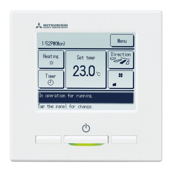
Page 9: Functions And Menu Items Of The Remote Control
6. Functions and menu items of the remote control Names and functions of sections on the R/C ⑤ ③ F2 switch ④ Operation lamp ⑥ ① Run/Stop switch ② F1 switch than the ① ② ③ ① Run/Stop switch ①, ② ... - Page 10 Names and functions of sections on the R/C * ① ② Icon display TOP screen ③ Menu button ⑤ Change set temp button ④ Change operation ⑥ mode button direction button ⑧ Timer button ⑦ Change fan speed button ⑨ Select the language button ⑩ Message display ⑪...
-
Page 11: Main Item
7. Main item Main menu Run ………………………………………………………………………………………… ………………………………………………………………………………………… ………………………………………………………………… ………………………………………………………………………… …………………………………………………………………… …………………………………………………………………… …………………………………………………………………… ………………………………………………………… <?> …………………………………………………………………… ………………………………………………………………… ……………………………………………………………………… Useful functions ……………………………………………………………………… …………………………………………………………………………… ………………………………………………………………………………………… …………………………………………………… ………………………………………………… …………………………………………………… ………………………………………………… …………………………………………………………………… …………………………………………………………………………… ……………………………………………………………………………… ………………………………………………………………………… ……………………………………………………………………… ………………………………………………………………………… Energy-saving setting ………………………………………………………………………………… …………………………………………………………………………… ………………………………………………………………… Motion sensor control ……………………………………………………………………... - Page 12 Main menu Service setting Installation date ………………………………………………………… …………………………………………………… …………………………………………………………………… ……………………………………………… …………………………………………………… ……………………………………………… ……………………………………………………… …………………………………………………… ………………………………………………………… Return air temp ………………………………………………………… ……………………………………………………………… ………………………………………………… Operation mode ………………………………………………………… …………………………………………………………………… Fan speed ……………………………………………………………… …………………………………………………………… ………………………………………………… …………………………………………………… ……………………………………………………… ……………………………………………………………… ……………………………………………………… ………………………………………………………… ……………………………………………………… ………………………………………………………………… ………………………………………………………… …………………………………………………… …………………………………………………………...
-
Page 13: Power On And Initial Setting
8. Power on and initial setting ・ ・ ⑴ ①⇒② Main ④ Main Caution ① ② used, tap the Main is not tapped, it keeps the screen Main ③⇒④⇒⑤ ①⇒⑧⇒⑤ ③ IU search on ④ ⑤... - Page 14 When the main and sub are set ⑥ ⑦ ⑧ ⑧⇒⑤ ①⇒② ⑦ ⑥ ⑤...
-
Page 15: Installation Settings And Test Run
9. Installation settings and test run Menu ⇒ ⇒ ⇒ ③ Installation date ① ② Installation date Installation date and tap the ⑤ ⑥ ④ カナ 漢字 Delete Delete ⑨ Drain pump test run ⑦ ⑧ Drain pump test run Drain pump test run... - Page 16 ⑩ ⑪ ⑫ Finish IU address OU address Ⅲ OU address IU address Ⅱ Ⅰ Ⅰ ⑫ Ⅱ ⑪ Finish Ⅲ ⑬ ⑭ IU rotation Details Details Enter Enter...
- Page 17 ⑮ Rotation details ⑯ hours and tap Enter and tap Enter ⑰ ・ ・...
-
Page 18: R/C Function Settings
10. R/C function settings Advice: It is valid when unit stops. Menu ⇒ ⇒ ⇒ ① ② ③ Fan speed Return air temp Operation mode ④ Main ⑤ Return air temp Return air temp : Master IU Master IU : :... - Page 19 ⑦ ⑧ ⑨ Menu Menu : : Direction Direction Auto Auto Room ○ ○ ⇒ ⑩ ⇒ ⑪ ⑫ Operation mode ⑩ ⑪ Operation mode Auto ⑭ Fan speed ⑬ ⑮ Fan speed All units Lo) ( Me) ( to plural indoor units connected in one system All units...
- Page 20 ⑯ ⑰ ⑱ Independent Independent ⑲ ⑳ ㉑ Auto selection switch will not Auto selection switch will not...
-
Page 21: Iu Settings
11. IU settings Advice: It is valid when unit stops. Menu ⇒ ⇒ ⇒ ① ② ③ Menu Menu IU select IU select All units All units ④ All units ⑤ ⑥ ④ Drain pump operation ⑦ ⑭ ⑧ ⑨ Fan circulator operation Auto operation mode... - Page 22 ⑩ ⑪ ⑫ ⑬ Pulse input ⑭ ⑮ ⑯ Pulse input...
- Page 23 ⑰ ⑱ ⑲ Intermittent Intermittent ⑳ ㉑ ㉒ Intermittent Intermittent...
- Page 24 ㉓ Drain pump operation ㉔ ㉕ Drain pump operation Operates * ㉗ Fan circulator operation ㉖ ㉘ Fan circulator operation...
- Page 25 ㉙ Auto operation mode ㉚ Auto rule selection set temp and the actual room Auto operation mode Auto rule selection Auto rule selection set temp and the actual room ㉛ ⇒ Room ⇒ ◆ ◆ ㉜ ⇒ tion 室 内 吸...
- Page 26 ㉝ ⇒ tion operation ⇒ Outdoor temp ◆ ㉞ ㉟ ㊱ ㊲ ㊳ ㊴...
- Page 27 ㊵ ㊶ ㊷ ㊸ ㊹ ⇒ Medium ⇒ ⇒ ⇒ Medium ⇒...
- Page 28 ㊺ ㊻ ㊼ Operation output キャンセル 次ペー ジ C N T C N T C N T C N T ㊽ ㊾ 前ペー ジ 次ペー ジ...
-
Page 29: Service & Maintenance
12. Service & Maintenance Menu ⇒ ⇒ ⇒ ③ IU address ① ② IU address IU address IU address OU address Indoor unit capacity display Operation data Error display 次ペー ジ 前ペー ジ 次ペー ジ ⇒④ ④ ⑤ ⑥ Fan operation 動作を選択... - Page 30 ⑩ ⑪ ⑫ Update Update Update Operation data Operation data Operation data Item Data Item Data Item Data Protection control Low pressure Display Display Display ⑮ Error display ⑬ ⑭ Error display Update Operation data Operation data Error history Operation mode Display anomaly data Item Data...
- Page 31 ⑲ ⑳ ㉑ Display anomaly data Display anomaly data Display anomaly data Item Data Item Data Item Data Outdoor air temp Low pressure Protection control ㉔ Erase anomaly data ㉓ ㉒ Display anomaly data Erase anomaly data Display anomaly data Item Data Item...
- Page 32 Erase IU address ㉚ ㉙ Erase IU address Use this to correct when the display and the touch ㉛ # ㉜ # ㉝ # Redo Finish Finish ⇒ ㉞ Indoor unit capacity display Indoor unit capacity display IU address tap the...
-
Page 33: Select The Language
13. Select the language 【Selecting the language with the button】 ① ② and tap the ■ Menu 【Selecting the language with the button】 Menu ⇒ ⇒ ①...
Need help?
Do you have a question about the RC-EX3A and is the answer not in the manual?
Questions and answers