Table of Contents
Advertisement
Quick Links
Advertisement
Chapters
Table of Contents

Related Manuals for Mitsubishi Heavy Industries eco touch RC-EX1


Summary of Contents for Mitsubishi Heavy Industries eco touch RC-EX1
- Page 1 eco touch REMOTE CONTROL RC-EX1 INSTALLATION MANUAL PJZ012D077...
-
Page 2: Table Of Contents
Contents 1. Safety Precautions ………………… 2 2. Accessories & Prepare on site …… 4 3. Remote control installation procedure …………………………… 4 Determine where to install the remote control .. 4 Installation procedure …………………………… 5 Main/Sub setting when more than one remote controls are used …………………………………... -
Page 3: Safety Precautions
1 . Safety Precautions This installation manual describes the installation methods and precautions related to the remote control. Use this manual together with the user’s manuals for the indoor unit, outdoor unit and other optional equipment. Please read this manual carefully before starting the installation work to install the unit properly. Safety precautions ●... - Page 4 When installing the unit at a hospital, telecommunication facility, etc., take measures to suppress electric noises. It could cause malfunction or break-down due to hazardous effects on the inverter, private power generator, high frequency medical equipment, radio communication equipment, etc. The influences transmitted from the remote control to medical or communication equipment could disrupt medical activities, video broadcasting or cause noise interference.
-
Page 5: Accessories & Prepare On Site
2 . Accessories & Prepare on site R/C main unit, wood screw (ø3.5 x 16) 2 pcs Accessories User’s Manual, Installation Manual Parts procured at site When the cable length is longer than Item name Q’ty Remark 100 m, the max size for wires used Switch box in the R/C case is 0.5 mm . -
Page 6: Installation Procedure
Request Be sure not to install R/C at a place where temperatures around the installation surface of R/C may differ largely from actual room temperature. Difference between detected temperature and actual room temperature could cause troubles. The correction for detected temperature by the R/C cannot offset such temperature difference because it corrects the detected temperatures itself. - Page 7 W hen wires are passed through the bottom case, fix the bottom case at 2 places on the switch box. ④ Upper side Upper side Switch box Switch box for 1 pc for 2 pcs Cut out the thin wall part at the screw mounting Bottom case...
-
Page 8: Main/Sub Setting When More Than One Remote Controls Are Used
If the hole is cut too large, moisture, dust or insects may enter. Seal gaps with putty or the like. F ix the bottom R/C case on a ④ flat surface with wood screws. I n case of the upper center, ⑤... - Page 9 Note: Connection to personal computer It can be set from a personal computer via the USB port (mini-B). Connect after removing the cover for USB port of upper case. Replace the cover after use. If dust, insect, etc. enters, it could cause electric shocks or breakdown.
-
Page 10: Functions And Menu Items Of Remote Control
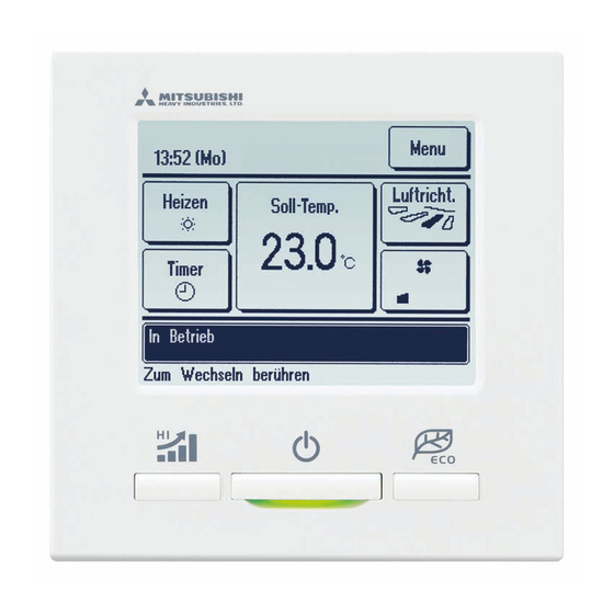
4. Functions and menu items of Remote control Names and functions of sections on R/C (Operating section) ⑤ LCD display (With backlight) switch ③ ④ Operation lamp ⑥ USB port (mini-B) ① switch ② switch Touch panel system, which is operated by tapping the LCD screen with a finger, is employed for any operations other than the ①... - Page 11 Names and functions of sections on R/C (Display) * All icons are shown for explanation. ① Clock, R/C name display ② Icon display TOP screen ③ Menu button ⑤ Change set temp ④ Change operation button mode button ⑥ Change flap ⑧...
- Page 12 Menu item Main menu …………………………………………… Basic operation Run/Stop ………………………………… Change operation mode ………………… Change set temp ………………………… Change flap direction …………………… Change fan speed ……………………… High power operation …………………… Energy-saving operation………………… …………………………………………… Energy-saving setting Sleep timer ……………………………… Peak-cut timer …………………………… Automatic temp set back ………………...
- Page 13 Main menu ( ◇ ) It is necessary to input the Service password for menu items showing. Installation settings ( ◇ ) …………………………………………………………………… 15 Installation date ………………………………………………… 16 Company information …………………………………………… 16 Test run …………………………………………………………… 17 Static pressure adjustment …………………………………… 18 Change auto-address ……………………………………………...
-
Page 14: The Indication When Power Source Is Supplied
5. The indication when power source is supplied Power on and initial setting Power on and initial setting Set the main and sub R/C units according to the display at the power on. (1) When the main and sub are not yet set, ①‰② Main/sub input screen is displayed. When tapping the [Main] or [Sub] button, initial setting starts. - Page 15 ⑤ TOP screen [Yes] Continue ‰⑥‰⑤ ⑥ Set continue acknowledge Change ‰⑦ [No] If the screen is not tapped for more than 15 seconds, the [Yes] (Continue) is selected and the display changes to the screen of ⑤ . [Yes] ‰⑧‰⑤ ⑦...
-
Page 16: Installation Settings
6. Installation settings Installation settings cover the following items. (1) Installation date: Register the date when the unit was installed. ➝ ⑦ (2) Company information: Enter the information of contact for service. ➝ ⑧ (3) Test run: Cooling test run, drain pump test run or compressor Hz fixed operation is performed. ➝ ⑪ (4) Static pressure adjustment: Static pressure is adjusted in case of connecting the duct type IU equipped with the external static pressure adjustment function. - Page 17 ⑤⑥ Display the installation settings screen. ⑤ Installation settings menu ⑥ Installation settings menu ⑦ Installation date ⑦ Installation date Enter the date when the unit was installed. ▲ ▼ Select the date with buttons, and tap the Set button. ⑧...
- Page 18 ⑩ Enter the Phone No. of the contact. ⑩ Enter the Phone No. of the contact Tap the Set button after the input. ⑪ Test run ⑪ Test run Select a test run item to be implemented. (a) Cooling test run: Operation can be made only in cooling mode. ➝ ⑫ (b) Drain pump test run ➝...
- Page 19 ⑮ Static pressure adjustment ⑮ Static pressure adjustment This is operable in case of connecting duct type IU equipped with the external static pressure adjustment function. Operating method is described in the installation manuals for the indoor units with this function. ⑯⑰...
- Page 20 ⑲ IU Back-up function ⑲ IU Back-up function In case of 2 sets of indoor units connected to one R/C, it is available to perform back-up operation with them. IU rotation: Operate 2 sets of indoor units alternately at every set time of operation interval.
-
Page 21: R/C Function Settings
7. R/C function settings R/C function settings cover the following items. These settings can be done only when the unit is stopped. (1) Main/Sub of R/C: Set the main or sub R/C . ➝ ⑧ (2) Return air temp: Set the detection method of return air temp for applying to thermo. rule*. ➝ ⑨ (3) R/C sensor: Set the operation mode to apply the temp detected with R/C sensor to thermo. - Page 22 ④ Display the service password input screen. ④ Service password input Enter the service password (4-digit number). The service password is “9999”. (Unable to change) ⑤⑥⑦ Display the R/C setting menu screens. ⑤ R/C setting menu 1 ⑥ R/C setting menu 2 ⑦...
- Page 23 ⑨ Return air temp ⑨ Return air temp Thermo. rule* is applied based on the temperature detected with the return air temp sensor of IU. When plural indoor units are connected to one R/C, the return air temp applied to the thermo. rule* can be selected. Individual: Thermo.
- Page 24 ⑫ Adjustment in cooling ⑫ Adjustment in cooling ⑬ Adjustment in heating ⑬ Adjustment in heating ⑭ Operation mode ⑭ Operation mode Enable or Disable can be set for each operation mode. If the cooling or heating is disabled, the auto is also disabled. ⑮...
- Page 25 ⑰ External input ⑰ External input Set the range to apply the external input received through CNT of either one IU to plural indoor units connected in one system Individual: This is applied only to the IU receiving CNT input. All units: This is applied to all indoor units connected.
- Page 26 ㉑ Auto set temp ㉑ Auto set temp Select Enable or Disable on the Auto temp setting screen. Enable: Auto set temp can be selected. Disable: Auto set temp cannot be selected. No select switch is displayed on the screen. ㉒...
-
Page 27: Iu Settings
8. IU settings IU settings cover the following items. These settings can be done only when the unit is stopped. (1) High ceiling: Set the fan speed for High ceiling operation. ➝ ⑪ (2) Filter sign: Set the time to display the filter sign. ➝ ⑫ (3) External input 1: Set the control at the time when the signal is input to the external input 1 (CNT) of IU. - Page 28 ②③ Main menu screen is displayed. ② Menu screen 1 Tap the “IU settings” on the menu screen. ③ Menu screen 3 ④ Display the service password input screen. ④ Service password input Enter the service password (4-digit number). The service password is “9999”. (Unable to change) ⑤...
- Page 29 ⑦ IU setting menu 2 ⑧ IU setting menu 3 ⑨ IU setting menu 4 ⑩ IU setting menu 5 ⑪ High ceiling ⑪ High ceiling Set the fan speed tap for the IU. It may not be available to set depending on IU models connected. —...
- Page 30 ⑫ Filter sign Standard ⑫ Filter sign No display None Setting 1 180Hr Setting 2 600Hr Set the time to display the filter sign. Setting 3 1,000Hr 1,000Hr Setting 4 Operation stop ⑬ External input 1 ⑬ External input 1 Set the control at the time when the signal is input to the external input 1 (CNT) of IU.
- Page 31 ⑰ Heating thermo-OFF temp adjustment ⑰ Heating thermo-OFF temp adjustment Adjust the temperature for judging to make thermostat ON or OFF during heating operation. Adjustable range is 0°C to +3°C. ⑱ Return air sensor adjustment ⑱ Return air sensor adjustment Adjust the temperature detected with the return air temp sensor.
- Page 32 ㉑ Anti-frost temp ㉑ Anti-frost temp Select the anti-frost control temperature. ㉒ Anti-frost control ㉒ Anti-frost control Set the fan control during the anti-frost control. Enable: The fan speed increases during the anti-frost control. Disable: The fan speed does not change during the anti-frost control. ㉓...
- Page 33 ㉕ Residual fan operation in heating ㉕ Residual fan operation in heating Select the residual fan operation time period after stopping and the thermo- OFF in heating mode. Setting1: 0.5 hr Setting2: 2 hrs Setting3: 6 hrs ㉖ Intermittent fan operation in heating ㉖...
- Page 34 ㉙ Auto operation mode ㉙ Auto operation mode ㉚ Auto rule selection Set the control method for the auto operation mode. Method of switching between cooling and heating during automatic operation can be selected. Auto1: Cooling and heating are switched based on the difference between the set temperature and the room temperature.
- Page 35 ㉜ Auto 2 details ㉜ Auto 2 details Set the temperatures switching to cooling and heating and the outdoor temp settings to limit in cooling and heating. “[Set temp - Temp switching to cooling] < [Indoor return air temp]” and “[Outdoor temp, cooling] <...
- Page 36 ㉞ Temp switching to cooling ㉞ Temp switching to cooling ㉟ Temp switching to heating In the Auto 1 and Auto 2, set the temperatures switching to cooling and heating. The switching temperatures can be set within the range of 1°C to 4°C. ㉟...
- Page 37 ㊴ Indoor temp set for heating ㊵ Thermo rule setting ㊵ Thermo rule setting Set the switching method and conditions for the thermo rule. ㊶ Standard/Outdoor temp basis ㊶ Standard/Outdoor temp basis Set the switching method for the thermo rule. Standard: The thermostat judges based on the indoor temperature and set temperature.
- Page 38 Thermo rule setting Cooling Thermo-OFF Heating Cooling offset offset Thermo-OFF Heating Outdoor temp. Outdoor temp. ㊹ Auto fan speed control ㊹ Auto fan speed control Set the switching range of the fan tap at the auto fan speed setting. Auto 1: The fan tap is changed in the range of High ‰ Medium ‰ Low. Auto 2: The fan tap is changed in the range of Powerful high ‰...
-
Page 39: Service & Maintenance
9. Service & Maintenance Service & Maintenance settings cover the following items. (1) IU address: Displays the “IU address” and “OU address” of the IU connected to the R/C. ➝ ⑦ (2) Next service date: Enter the next service date (dd/mm/yy). ➝ ⑨ (3) Operation data: Operation data are displayed when the indoor unit No is selected. - Page 40 ⑤⑥ Service & maintenance menus are displayed. ⑤ Service & maintenance menu 1 ⑥ Service & maintenance menu 2 ⑦ IU address ⑦ IU address IU address, name of IU and OU address of the units connected to the R/C are displayed.
- Page 41 ⑩ Service message ⑪ Operation data, IU select ⑪ Operation data, IU select If plural IUs are connected to the R/C, select the IU to be displayed. If only one IU is connected, the IU select screen is not displayed. ⑫...
- Page 42 ⑬ Individual display ⑬ Individual display Data of selected items are updated and displayed automatically. ⑭ Error display ⑭ Error display Error history and data at occurrence of error saved in the R/C are displayed. (a) Error history (b) Display anomaly data (c) Erase anomaly data (d) Reset periodical check ⑮⑯...
- Page 43 ⑱ Display anomaly data ⑱ Display anomaly data Operation data taken just before the occurrence of error are displayed. Display items are same as the <Operation data items> (refer to ⑫ ). ⑲ Erase anomaly data ⑲ Erase anomaly data When tapping the [Yes] button on the Erase anomaly data acknowledge screen, the anomaly data are erased.
- Page 44 ㉒ Save IU settings ㉒ Save IU settings All settings of IUs connected to the R/C are saved in the R/C. IU setting item for saving High ceiling Fan control in heating thermo-OFF Control pressure adjust Filter sign Anti-frost temp Auto operation mode External input 1 Anti-frost control...
- Page 45 ㉖ Special settings ㉖ Special settings Erase IU address: Memory of the IU address for multi (KX) unit is erased. CPU reset: Microcomputers of IU and OU connected are reset (State of restoration after power failure). Initializing: Settings on R/C and IU connected are initialized (State of factory default).
- Page 46 ㉚ Touch panel calibration ㉚ Touch panel calibration Use this when the display and the touch position are not matched. Tap the [Start] button to start calibration Tap the center of [+] according to the prompt. Tap [+] on the lower right ㉛...
-
Page 47: Select The Language
10. Select the language ① Tap the Menu button on the TOP screen. ① TOP screen ②③ Main menu screen is displayed. ② Menu screen Tap the “Select the language” on the menu screen. ③ Menu screen #2 ④ When the Input password screen is displayed, enter the ④... - Page 48 eco touch REMOTE CONTROL RC-EX1 QUICK REFERENCE Quick reference ENGLISH Thank you very much for your purchasing the eco touch REMOTE CONTROL for our packaged air conditioner. This user’s manual describes cautions for safety. Please read this manual carefully before use in order to operate the unit properly.
- Page 49 INSTALLATION For the operation part of this Quick reference refer to page 18. Refer to the “Installation manual” (in CD-R) for details. Contents 1. Safety Precautions ………………… 3 2. Accessories & Prepare on site …… 4 3. Remote control installation procedure …………………………… 4 4.
-
Page 50: Safety Precautions
1 . Safety Precautions This installation manual describes the installation methods and precautions related to the remote control. Use this manual together with the user’s manuals for the indoor unit, outdoor unit and other optional equipment. Please read this manual carefully before starting the installation work to install the unit properly. -
Page 51: Accessories & Prepare On Site
2 . Accessories & Prepare on site R/C main unit, wood screw (ø3.5 x 16) 2 pcs Accessories User’s Manual, Installation Manual Parts procured at site When the cable length is longer than Item name Q’ty Remark 100 m, the max size for wires used Switch box in the R/C case is 0.5 mm . - Page 52 Installation procedure Dimensions (Viewed from front) PCB side (Viewed from rear) Fixing holes Sensor USB port Terminal Block ① ② To remove the upper case from the bottom cases of R/C C onnect wires from X and Y terminals of R/C to X and Y ·...
- Page 53 Main/Sub setting when more than one remote control are used Main-Sub setting for use of two or more R/Cs Up to two units of R/C can be used at the maximum for 1 indoor unit or 1 group. One is main R/C and the other is sub R/C. Operating range is different depending on the main or sub R/C.
-
Page 54: The Indication When Power Source Is Supplied
4. The indication when power source is supplied Power on and initial setting Power on and initial setting Set the main and sub R/C units according to the display at the power on. (1) When the main and sub are not yet set, ① ② Main/sub input screen is displayed. When tapping the [Main] or [Sub] button, initial setting starts. -
Page 55: Menu Items
3. Menu items ( ◇ ) It is necessary to input the Service password for menu items showing. Main menu …………………………………………… Basic operation Refer to User’s manual …………………………………………… Energy-saving setting Refer to User’s manual …………………………………………… Individual ap control Refer to User’s manual ……………………………………………... -
Page 56: Installation Settings
Installation settings (Service password) Installation settings cover the following items. ⑦ (1) Installation date: Register the date when the unit was installed. ⑧ (2) Company information: Enter the information of contact for service. ⑪ (3) Test run: Cooling test run, drain pump test run or compressor Hz fixed operation is performed. (4) Static pressure adjustment: Static pressure is adjusted in case of connecting the duct type IU equipped with the external static pressure ⑮... - Page 57 ⑫ Cooling test run ⑬ Drain pump test run ⑭ Compressor Hz fixed operation ⑫ Cooling test run ⑬ Drain pump test run ⑭ Compressor Hz fixed operation When the room temperature is too low to start the Drain pump can be operated independently. Compressor operation frequency of the inverter outdoor unit can be fixed.
-
Page 58: R/C Function Settings
⑳ Set the timer for changeover ㉑ Set the temp diff. for back-up ⑳ Set the timer for changeover ㉑ Set the temp diff. for back-up In IU rotation function, the timer to changeover the operation of 2 indoor units In IU capacity back-up function, the temperature difference between the is set. - Page 59 ⑧ Main/Sub of R/C ⑨ Return air temp ⑨ Return air temp ⑧ Main/Sub of R/C Thermo. rule* is applied based on the temperature detected with the return air temp sensor of IU. Use this when changing the Main/ When plural indoor units are connected to one R/C, the return air temp applied to the thermo. rule* can be Sub setting of R/C.
-
Page 60: Iu Settings
⑮ External input ⑯ Ventilation setting ⑰ Flap control ⑰ Flap control ⑮ ⑯ External input Ventilation setting Set the range to apply the external input Set this when a ventilation device is connected. Set the flap stop control. received through CNT of either one IU to plural Disable: No ventilation device is Stop at fixed position: The flap can be set to... - Page 61 ① TOP screen ② Menu screen 1 ③ Menu screen 3 ① Tap the Menu button on the TOP ②③ Main menu screen is displayed. screen. Tap the “IU settings” on the menu screen. ④ Service password input ⑤ Select IU ⑥...
- Page 62 ⑰ Drain pump operation ⑱ Residual fan operation in cooling ⑲ Residual fan operation in heating ⑰ Drain pump operation ⑱ Residual fan operation in cooling ⑲ Residual fan operation in heating Set the operation mode to operate the drain pump. Standard (in cooling &...
-
Page 63: Service & Maintenance
㉗ Auto fan speed control ㉘ IU overload alarm ㉗ Auto fan speed control ㉘ IU overload alarm Set the switching range of the fan tap at the auto fan speed setting. When the room temperature differs to some extent from the setting tempera- Auto 1: The fan tap is changed in the range of High Medium Low. - Page 64 ⑩ Operation data, IU select ⑩ Operation data, IU select ⑪ Operation date If plural IUs are connected to the R/C, select the IU to be displayed. If only one IU is connected, the IU select screen is not displayed. ⑪...
- Page 65 OPERATION Refer to the “User's manual” (in CD-R) for details. Contents 1. Safety Precautions ……………… 19 2. Functions and menu items of Remote control (R/C) …………… 20 3. Menu items ………………………… 22 3.1 Basic operation ……………… 22 3.2 Energy-saving settings ……… 25 3.3 Individual ap control ………...
-
Page 66: Safety Precautions
1. Safety precautions Safety precautions Please read the precautions written here carefully to operate the unit properly. You are required to observe these fully because every item of these instructions is important for safety. Failure to follow these instructions may result in serious consequences such as death, WARNING severe injury, etc. -
Page 67: Functions And Menu Items Of Remote Control (R/C)
2. Functions and menu items of the remote control Names and functions of sections on the R/C (Operating section) ⑤ LCD display (With backlight) ① switch (Run/Stop switch) If the backlight is ON setting, when the screen is tapped while the backlight is turned off, the One push on the button starts operation and backlight only is turned on. -
Page 68: Menu Items
3. Menu items Main menu ( ◇ ) It is necessary to input the Administrator password for menu items showing. Basic operation Run/Stop ………………………………………………………… 22 Charge operation mode ………………………………………… 22 Change set temp ………………………………………………… 22 Change ap direction …………………………………………… 23 Change fan speed ………………………………………………... -
Page 69: Run/Stop
Run/Stop Run Stop When the operation stops, all operation buttons on the screen turn off. When the set lighting time of backlight Push the switch. Push the switch. ( ☞ page 29) is counted up, the backlight turns off. Operation lamp (green) lights and operation starts. -
Page 70: Change Ap Direction
Change ap direction ■ Since the flap is controlled automatically in the following operation, it may differ from the display on the R/C. When the room temperature is higher than the set temp (In case of the heating operation) When the “In operation for heating standby” or “In operation for defrosting”... - Page 71 Restrictions on the sub R/C Main Basic operation High power operation Energy-saving operation Energy-saving setting Individual flap control External ventilation Filter sign reset Initial settings Timer Weekly timer Home leave mode Administrator settings *1 Warming up function cannot be set. Installation settings *2 R/C display setting, Set temp display and Change administrator R/C settings...
-
Page 72: Energy-Saving Settings
Energy-saving settings (Administrator password) T ap the “Energy-saving setting” on the main menu W hen the Input password screen is displayed, enter the Tap the Menu button on the TOP screen.å administrator password. screen. Note After entering the administrator password (4-digit number), tap the button. -
Page 73: Automatic Temp Set Back
D etail setting screen for the timer setting contents is S et the Start time. Set the End time. displayed. ▲ ▼ ▲ ▼ Set the hour and minute with the Set the hour and minute with the ... -
Page 74: Individual Ap Control
Individual ap setting Motion range (upper and lower limit positions) of the flap at each air outlet can be set at a desired range individually. ■ When the R/C is set as the sub R/C, the individual flap control cannot be set. ■... -
Page 75: Initial Settings
External ventilation Tap the Menu button on the TOP screen. T ap the “External ventilation” on the main menu The External ventilation screen is displayed. If the Venti. On button is taped, the ventilation screen. ■ The ventilation operation is enabled in case that the External operation starts. -
Page 76: Timer
■ Backlight ■ Controller sound T ap the “Backlight” on the Initial settings menu screen, T ap the “Controller sound” on the Initial settings menu screen, Tap the ON or OFF for the backlight lighting and the lighting Period (5 – 90 Tap ON or OFF for the controller sound. -
Page 77: Set Off Timer By Hour
Tap a desired operation mode. S elect a desired temperature (at 1°C intervals) with Tap a desired fan speed. ▲ ▼ buttons. Or tap the Auto If the No setting button is tapped, it operates at If the No setting button is tapped, it starts button and select the auto temp setting. -
Page 78: Weekly Timer
Weekly timer Note · The Clock setting ( ☞ page 27) must be made when the weekly timer is used. · The weekly timer can be set from the main R/C only. ■ T here are cases that the Input password screen is displayed by the Permission/Prohibition setting. -
Page 79: Select The Language
14 15 Display the setting contents check screen ( ☞ Display the group setting acknowledge screen. To register the setting, tap the Enter button. Tap the Yes and save the setting. ① In case of group setting (Weekdays, Sat/Sun, All days setting) The display changes to a day of the week setting check screen after saving. -
Page 80: Maintenance Of Unit And Lcd
Maintenance of Unit and LCD ■ W ipe the surface of LCD and main body of the remote control with a dry cloth when cleaning is required. ■ I f the dirt on the surface cannot be removed, soak the cloth in neutral detergent diluted with water, squeeze the cloth tightly, and clean the surface. Wipe the surface with a dry cloth then. Request Do not use any paint thinner, organic solvent, or strong acid. - Page 81 3rd Floor Thavies Inn House 3-4 Holborn Circus London EC1N 2HA, ENGLAND Tel : +44-20-7842-8171 Fax : +44-20-7842-8104 http ://www.mhie.com MITSUBISHI HEAVY INDUSTRIES AIR - CONDITIONERS AUSTRALIA, PTY. LTD. 9C Commercial Road Kingsgrove NSW 2208 PO BOX 318 Kingsgrove NSW 1480 Tel : +61-2-8571-7977 Fax : +61-2-8571-7992 http ://www.mhiaa.com.au...
Need help?
Do you have a question about the eco touch RC-EX1 and is the answer not in the manual?
Questions and answers