
Related Manuals for Fronius FPA 2020 Orbital


Summary of Contents for Fronius FPA 2020 Orbital
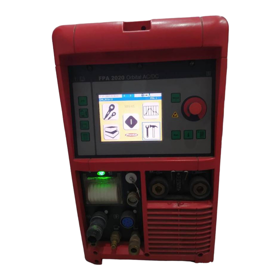
- Page 1 / Perfect Welding / Solar Energy / Perfect Charging Operating instructions, FPA 2020 Orbital Spare parts list TIG power source 42,0410,1406 V08 - 04082016...
- Page 3 Read the manual carefully and you will soon be familiar with all the many great features of your new Fronius product. This really is the best way to get the most out of all the advantages that your machine has to offer.
- Page 5 Safety rules DANGER! “DANGER!” indicates an imminently hazardous situation which, if not avoided, will result in death or serious injury. This signal word is to be limited to the most extreme situations. This signal word is not used for property damage hazards unless personal injury risk appropriate to this level is also involved.
- Page 6 General remarks Any malfunctions which might impair machine safety must be eliminated (continued) immediately - meaning before the equipment is next switched on. It’s your safety that’s at stake! Utilisation for The machine may only be used for jobs as defined by the “Intended intended purpose purpose”.
- Page 7 Obligations of Before starting work, all persons to be entrusted with carrying out work with personnel (or on) the machine shall undertake to observe the basic regulations on workplace safety and accident prevention to read the sections on “safety rules” and the “warnings” contained in this manual, and to sign to confirm that they have understood these and will comply with them.
- Page 8 Protection for “Protective clothing” also includes: yourself and protecting your eyes and face from UV rays, heat and flying sparks with other persons an appropriate safety shield containing appropriate regulation filter glass (continued) wearing a pair of appropriate regulation goggles (with sideguards) behind the safety shield wearing stout footwear that will also insulate even in wet conditions protecting your hands by wearing appropriate gloves (electrically insula-...
- Page 9 Hazards from The harmfulness of the welding fumes will depend on e.g. the following noxious gases components: and vapours the metals used in and for the workpiece (continued) the electrodes coatings cleaning and degreasing agents and the like For this reason, pay attention to the relevant Materials Safety Data Sheets and the information given by the manufacturer regarding the components listed above.
- Page 10 Hazards from Do not loop any cables or other leads around your body or any part of your mains and weld- body. ing current (continued) Never immerse the welding electrode (rod electrode, tungsten electrode, welding wire, ...) in liquid in order to cool it, and never touch it when the power source is ON.
- Page 11 Stray welding When using current supply distributors, twin head wire feeder fixtures etc., currents please note the following: The electrode on the unused welding torch/welding (continued) tongs is also current carrying. Please ensure that there is sufficient insula- ting storage for the unused welding torch/tongs. In the case of automated MIG/MAG applications, ensure that only insulated filler wire is routed from the welding wire drum, large wirefeeder spool or wirespool to the wirefeeder.
- Page 12 EMI Precautions Electromagnetic fields may cause as yet unknown damage to health. Effects on the health of persons in the vicinity, e.g. users of heart pace- makers and hearing aids Users of heart pacemakers must take medical advice before going anywhere near welding equipment or welding workplaces Keep as much space as possible between welding cables and head/body of welder for safety reasons...
- Page 13 Particular danger When hoisting the machines by crane, only use suitable manufacturer- spots supplied lifting devices. (continued) Attach the chains and/or ropes to all the hoisting points provided on the suitable lifting device. The chains and/or ropes must be at an angle which is as close to the vertical as possible.
- Page 14 Safety precauti- A machine that topples over can easily kill someone! For this reason, always ons at the instal- place the machine on an even, firm floor in such a way that it stands firmly. lation site and An angle of inclination of up to 10° is permissible. when being transported Special regulations apply to rooms at risk from fire and/or explosion.
- Page 15 Safety precauti- If any damage occurs in cases where other coolants have been used, the ons in normal manufacturer shall not be liable for any such damage, and all warranty operation claims shall be null and void. (continued) Under certain conditions, the coolant is flammable. Only transport the coolant in closed original containers, and keep it away from sources of ignition.
- Page 16 Safety markings Equipment with CE-markings fulfils the basic requirements of the Low- Voltage and Electromagnetic Compatibility Guideline (e.g. relevant product standards according to EN 60 974). . Equipment marked with the CSA-Test Mark fulfils the requirements made in the relevant standards for Canada and the USA. Data security The user is responsible for the data security of changes made to factory settings.
-
Page 17: Table Of Contents
Contents General ................................. 3 Principle ..............................3 Device concept ............................3 Application areas ............................3 Warning notices affixed to the device ...................... 4 Controls and connections ..........................5 Control panel ............................5 Symbol bar ............................... 7 Connections, switches and system add-ons ....................8 FPA 2020 power source ........................... - Page 18 Every 6 months ............................61 Every 12 months ............................ 61 Disposal ..............................61 Validity of „General Delivery and Payment Conditions“ ................61 Technical Data ............................. 62 Special voltages ............................. 62 Power source ............................62 Integral cooling unit ..........................63 Fronius Worldwide...
-
Page 19: General
General Principle The FPA 2020 is a completely digitised, microprocessor-controlled inverter power source for orbital welding. An active power source manager is coupled with a digital signal processor, and together they control and regulate the entire welding process. The actual data are measured continuously, and the device responds immediately to any changes. -
Page 20: Warning Notices Affixed To The Device
NOT be removed or painted over. device Type Art.No. A-4600 Wels Ser.No. www.fronius.com IEC 60974-1/-2/-3 EN 50199 3 A / 10.1 V - 200 A / 17,9 V X(40°C) 100% 200 A 150 A 130 A 9.5 kV... -
Page 21: Controls And Connections
Controls and connections Control panel NOTE! As a result of firmware updates, you may find that there are functions available on your unit that are not described in these operating instructions or vice versa. Certain illustrations may also differ slightly from the actual controls on your unit. - Page 22 Control panel No. Function (continued) (2) „Next“ key for scrolling to the next menu window (3) Touchscreen Displays various context-sensitive keypads (4) F1 key freely programmable function key (in the „setup and system parameter“ menu) (5) Shielding gas and cooling key Opens the „shielding gas and cooling“...
-
Page 23: Symbol Bar
Symbol bar WARNING!Operating the equipment incorrectly can cause serious injury and damage. Do not use the functions described here until you have read and completely understood all of the following documents: These operating instructions all the operating instructions for the system components, especially the „Safety Rules“... -
Page 24: Connections, Switches And System Add-Ons
Connections, switches and system add-ons WARNING! Operating the device incorrectly can cause serious injury and damage. Do not use the functions described here until you have read and completely understood all of the following documents: these Operating Instructions all the operating instructions for the system components, especially the “Safety Rules”... - Page 25 FPA 2020 power No. Function source (9) Wire-feed unit connection (continued) for a cold wire feeder or a wire-feed unit incorporated into the orbital welding gun (10) Shielding gas output connection for the orbital welding gun or the TIG welding torch (11) Water flow connection for the orbital welding gun or the TIG welding torch (12) Water return connection...
-
Page 26: Remote Control Unit
Remote control WARNING! Operating the device incorrectly can cause serious injury and unit damage. Do not use the functions described here until you have read and completely understood all of the following documents: these Operating Instructions all the operating instructions for the system components, especially the “Safety Rules”... - Page 27 Remote control (3) Group selection key unit Press (+) or (-) to access the selec- (16) (continued) tion menu to select the program group. The previously selected group (16) appears. Press (+) or (-) again to select the desired group (16) of welding pro- grams.
- Page 28 Remote control Important! To exit the selection menu without changing the original settings, press the unit „Stop“ key (12). (continued) (5) Welding current key For changing the current during welding according to the “welding current” parame- ter in dialog window 233 “value adjustment” as shown in the section headed “setup and system parameters”...
- Page 29 Remote control If the „ROLL-UP“ parameter in dialog window 221 „Parameters for start point“ (see unit „Parameter settings“) is set to „INACTIVE“, the welding process can be activated by (continued) simply pressing the key (11) once. The defined start position is not moved to and the hosepack is not rolled up.
-
Page 30: Display Idle
Display idle Date and time Name of the currently loaded welding program Orbital welding gun type READY/NOT READY - power source ready to weld, or error needs to be rectified Pos - position of the orbital welding gun [°] / welding speed [cm/min] Wire feed speed [cm/min] Display after Number appearing next to „POSITIO-... -
Page 31: Display During Upslope
Display during Number appearing next to „START, upslope UPSLO“ is the time elapsed since welding started Pos - position of the orbital welding gun [°] Spd - welding speed [cm/min] Cur - welding current [A] Volt - welding voltage [V] Display during Number appearing next to „WEL- welding... -
Page 32: Before Commissioning
Before commissioning WARNING! Operating the device incorrectly can cause serious injury and damage. Do not use the functions described here until you have read and completely understood all of the following documents: these Operating Instructions all the operating instructions for the system components, especially the “Safety Rules”... -
Page 33: Commissioning
Commissioning WARNING! An electric shock can be fatal. If the device is plugged into the mains electricity supply during installation, there is a high risk of very serious injury and damage. Only carry out work on the device when the mains switch is in the „O“ position, the device is unplugged from the mains. -
Page 34: Establishing A Connection To The Workpiece
Establishing a Turn the mains switch to the „O“ position connection to the Plug the earthing (grounding) cable into the (+) current socket and twist to fasten it workpiece With the other end of the earthing (grounding) cable, establish a connection to the workpiece Connecting the Turn the mains switch to the „O“... -
Page 35: Menus With Direct Selection
Menus with direct selection Principle You can call up individual menus directly using keys on the control panel. F1 key F1 calls up a user-defined function. The following functions are available: Active alarm page Alarm history Move to starting position Save screenshot to USB Water pump OFF/ON For more detailed information on how to assign a function to the F1 key, please refer to... -
Page 36: Data Transfer" Menu
„Shielding gas Important! If the „OFF“ setting has been selected, the coolant pump will be in „AUTO“ and cooling“ mode after every power source restart provided that no gas-cooled welding torch is menu connected. (continued) To test the coolant pump Select “AUTO”... -
Page 37: Printer Configuration" Menu
„Printer configu- Open the menu by pressing the „Printer configuration“ key ration“ menu Provide the following information: „Realvalue Printout“ for relevant process data. Options include: No PrintOut Printer Prints to paper using the integral printer USB Stick No printing occurs. Instead, the relevant data is saved to the USB stick. - Page 38 „Printer configu- Example of „Realvalue Printout“ on paper ration“ menu (continued) Example of „Realvalue Printout“ as a .txt file for USB stick...
- Page 39 „Printer configu- Example of „Parameter Printout“ on paper ration“ menu (continued)
- Page 40 „Printer configu- Example of „Parameter Printout“ as a .txt file for USB stick ration“ menu (continued)
- Page 41 „Printer configu- Example of „Alarm Printout“ and „Start-Stop Printout“ on paper ration“ menu (continued) Example of „Alarm Printout“ and „Start-Stop Printout“ as .txt file for USB stick If „Start-Stop Printout“ has been selected, the following is printed every hour:...
-
Page 42: Alarms And Device-Specific Data
Alarms and Open the menu by pressing the „i“ key (9) device-specific Version numbers of the main modules data To display the present alarms, touch the „ALARMS“ button Current alarms These could be faults or application errors that have not yet been rectified. To display the saved alarms, touch the „HISTORY“... - Page 43 Alarms and In the first window, touch the „i“ key device-specific on the „HEAD.INFO“ button to call up data the orbital welding gun data. (continued) Important! The fields contained in this window are not controls and are for display purposes only. Diameter min.
- Page 44 Alarms and WARNING! Operating the device incorrectly can cause serious injury and device-specific damage. Do not use the functions described here until you have read and data completely understood all of the following documents: (continued) these Operating Instructions all the operating instructions for the system components, especially the “Safety Rules”...
-
Page 45: Main Menu
Main menu Safety CAUTION! Risk of injury and damage from electric shock. As soon as the mains switch is in the „I“ position, the tungsten electrode of the orbital welding gun is LIVE. Make sure that the tungsten electrode does not touch any persons or electrically conducting or earthed parts (e.g. -
Page 46: Selection Window
Selection window The selection window offers the following menus: (1) Orbital welding gun/manual welding torch (2) Synergic (characteristic) (3) Setup and system parameters (4) Parameter settings If a TIG welding torch has been selected instead of the orbital welding gun, the following symbol appears (4) as follows: (5) Weld Entry (6) shows the currently selected orbital welding gun or manual torch. -
Page 47: Orbital Welding Gun
Orbital welding gun Calling up the To select an orbital welding gun or „orbital welding welding torch, call up the orbital gun“ menu welding gun menu (1). Selecting the Select the desired type of orbital type of orbital welding gun welding gun (2) Open orbital welding gun (3) Closed orbital welding gun... -
Page 48: Selecting The Type Of Manual Welding Torch
Selecting the For gas-cooled welding torches, call type of manual up the „GAS M. TORCH“ entry welding torch For water-cooled welding torches, select the „WATER M. TORCH“ entry Important! For gas-cooled or water- cooled welding torches, Gas-cooled: standard setting for coolant pump is “OFF”. -
Page 49: Synergic
Synergic Calling up the Call up the „Synergic“ menu (2) „Synergic“ menu Principle In synergic mode, it is sufficient merely to enter a few well-known settings for the arc process. Using this information, the power source calculates all other settings for an optimum welding result. - Page 50 Entering parame- Make the following settings in the „Tack ters Program“ window: (continued) „Tackpoints“ OFF - tacking deactivated 1 ..20 - number of tack points “Tack.Welding time” - duration of welding current for a tack point [s] “Position 1st Tackpoint” - position of the first tack point [degrees] „Tack Gas preflow“...
-
Page 51: Setup And System Parameters
Setup and system parameters Calling up the Call up the „Setup and system para- „Setup and meters“ menu (3) system parame- ters“ menu A detailed description of the menus is provided in the following sections. Principle The „Setup and system parameters“ menu allows users to adjust the power source and orbital welding gun specifically to their requirements. -
Page 52: Changing Password
Logging on a Important! Only an administrator is authorised to assign user permissions. If a user’s different user, details have been changed, the user can no longer log on using his original user details. and changing the password To protect the power source from parameter changes: (continued) Lock the power source by touching the padlock symbol (7) The power source goes immediately into “Locked”... -
Page 53: User-Specific Settings
User permissions If required, press the „RESET USER“ button to reset the settings to their original (continued) status Use the „Op.-“ and „Op. +“ buttons to call up the settings for others users Use the „BACK“ button to go back to the „Change Operator“ window In the „Change Operator“... -
Page 54: Ignition Parameters
Ignition parame- Provide the following information: ters „Reverse P. Ignition“ - reverse polarity ignition ON: activate OFF: deactivate “tAC” - pulsed ignition. Pulsed ignition is activated automatically when selecting a tack program. Important! For more detailed information on the tack program, please refer to the „Synergic“... -
Page 55: Value Adjustment
Welding mode & Use the CALOTTE key to activate tungsten balling (cap shaping) (continued) The automatic cap-shaping function ensures that the optimum shape of electrode tip is formed automatically during the welding start-up. A separate cap-shaping operation on a test workpiece is no longer necessary. Important! No further cap-shaping is needed at the next welding start-up. -
Page 56: Welding Direction And Wirefeeding
Welding direction Provide the following information: and wirefeeding Welding direction Clockwise Anti-clockwise Important! Only closed welding guns with no wirefeeding support the anti- clockwise welding direction. Manual speed - welding speed in manual mode [cm/min] Rapid motion speed - high-speed welding [as % of the maximum welding speed of the orbital gun] Wire inching Use the „WIRE“... -
Page 57: Parameter Settings
Parameter settings Calling up the Call up the „Parameter settings“ menu „Parameter settings“ menu Principle The parameter settings allow the user to enter or correct the most important parameters for the orbital welding process. Waveform para- Provide the following information: meters for TIG „Step Mode“... -
Page 58: Waveform Parameters For Orbital Welding Gun
Waveform para- meters for TIG manual torch (continued) Important! If the „2-step mode“ has been set in the previous window, the left-hand window applies. For the „4-step mode“, the right-hand window applies. I-S - starting current [A] t-S - time for starting current [s] UPS - time for upslope [s] dSL - time for downslope [s] I-E - final current [A]... -
Page 59: Parameters For Pulsing And Welding Speed
This window allows the user to divide the Parameters for pulsing and travel path into several segments. For welding speed each of these segments, the parameters listed below for pulses and welding speed can be set individually. To create several segments, proceed as follows: In the “Seg.Path”... -
Page 60: Calling Up Parameters For Wirefeeding Or Ac Welding
Parameters for „Roll up Path“ [°] - anti-clockwise roll-up path for the hosepack, in degrees from the start point vertex (continued) „Start delay“ [s] - time between start of welding current and the point when the orbital welding gun starts rotating „Driving Downslope“... -
Page 61: Parameters For Wirefeeding
Parameters for Provide the following information: wirefeeding „Wire start“ - delay time between start of welding current and start of wire- feeding [s] „Wire Puls Setv;“ - wire feed speed during the pulse phase [cm/min] „Wire Back Setv;“ - wire feed speed during the background current phase [cm/min] „Wire stop“... -
Page 62: Orbital And Tig Welding
Orbital and TIG welding Safety WARNING! Operating the device incorrectly can cause serious injury and damage. Do not use the functions described here until you have read and completely understood all of the following documents: these Operating Instructions all the operating instructions for the system components, especially the “Safety Rules”... -
Page 63: Controlling And Monitoring The Welding Process
Controlling and WARNING! Automatically starting machines can cause serious injury and monitoring the damage. welding process In addition to these operating instructions, the robot and welding system manufacturer’s safety rules must also be observed. For your personal safety, ensure that all protective measures have been implemented and will remain in place for the duration of your stay within the working area of the orbital wel- ding gun. -
Page 64: Correcting The Welding Process
Correcting the This window appears when a change is welding process made on the remote control. For every segment, e.g. S1, the latest change to the original value is shown. For example, if the „current“ for segment „S1“ has been changed by 4 A, the digit „4“... -
Page 65: Troubleshooting
Troubleshooting General The digital power sources are equipped with an intelligent safety system. This means that apart from the fuse for the coolant-pump, it has been possible to dispense with melting-type fuses entirely. After a possible malfunction or error has been remedied, the power source can be put back into normal operation again without any melting-type fuses having to be changed. -
Page 66: Alarms And Error Messages
Alarms and error Group 001 messages 001 - Alarms are bypassed 002 - Internal connection problem Internal communication problem in the processors 003 - Gateway Timeout Faulty connection to the gateway 004 - USB Problem retrieving data from USB stick 005 - Low Gas Pressure Alarm for shielding gas monitor 006 - Power supply... - Page 67 Alarms and error Group 003 messages (continued) Alarms and error messages in Group 3 are internal errors that need to be rectified by a service engineer. Group 004 Alarms and error messages in Group 4 appear when welding is stopped. 001 - IR: RECE Error von UST (Error from UST) LocalNet: error number...
- Page 68 Alarms and error Group 005 messages 001 - Weldhead no rotation (continued) No rotation taking place, despite a command being sent 002 - Wire Feeder Wire not being transported, despite a command being sent 003 - Motor.Curr.Weldhead The analog entry value for the motor current is too high. Check rotation. 004 - Motor.Curr.Wire The analog entry value for the motor current is too high.
- Page 69 Alarms and error To deactivate further error-related alarms: Touch the touchscreen messages (continued) A symbol bar appears (1) Use the arrow keys (2) to select the alarm concerned Select the padlock symbol (3) in the symbol bar (1) The alarm concerned is greyed out To reactivate the alarm, select it again using the arrow keys (2) and touch the „padlock symbol“...
-
Page 70: Displayed Service Codes
Displayed service If an error message that is not described here appears on the displays, then the fault is codes one that can only be put right by a service engineer. Make a note of the error message shown in the display, and of the serial number and configuration of the power source, and get in touch with our After-Sales Service, giving them a detailed description of the error. -
Page 71: Power Source
Power source no | Arc Cause: Arc-break Remedy: Restart welding; clean workpiece surface. no | H2O Cause: Cooling unit flow watchdog has been triggered Remedy: Check the cooling unit; if necessary, top up the coolant or bleed the water flow as described in “Putting the cooling unit into service” hot | H2O Cause: Thermostat on cooling unit has tripped... - Page 72 Power source Nothing happens when welding starts (continued) Mains switch is ON and indicators are lit up Cause: The control plug is not plugged in Remedy: Plug in the control plug Cause: Orbital welding gun, torch or control line defective Remedy: Replace orbital welding gun or welding torch No shielding gas or forming gas...
- Page 73 Power source Water flow too low or non-existent (continued) Cause: Coolant level too low Remedy: Top up with coolant Cause: Constriction or foreign body in cooling circuit Remedy: Remove constriction or foreign body Cause: Coolant pump fuse defective Remedy: Replace coolant pump fuse Cause: Coolant pump defective Remedy:...
- Page 74 Power source no | H2O (continued) The cooling unit flow watchdog (option) has been triggered. The error message appears on the power source control panel. Cause: Coolant flow problem Remedy: Check the cooling unit; if necessary, top up the coolant or bleed the water flow as described in “Putting the cooling unit into service”...
-
Page 75: Care, Maintenance And Disposal
NOTE! If water-cooled torches are operated without coolant, this will normally result in a fault in the torch body or hosepack. Fronius shall not be liable for any damage resulting from such action. In addition, no warranty claims will be... -
Page 76: Every Week
If the coolant level is below the „min“ mark, top up with coolant. Fig. 11 Symbol for checking coolant level NOTE! Use only original Fronius coolant when filling cooling units. Other coolants are not recommended for electrical conductivity or compatibility re- asons. -
Page 77: Every 6 Months
Important! Coolant must not be disposed of in the public sewage system. Fig. 13 Change coolant symbol Use only original Fronius coolant (item no. 40,0009,0046) when refilling the cooling unit. Dispose of in accordance with the applicable national and local regulations. Disposal Validity of „Gene-... -
Page 78: Technical Data
Technical Data For devices designed for special voltages, the technical data on the rating plate applies. Special voltages Power source Mains voltage 230 V Mains voltage tolerance -20% / +15 % Mains frequency 50 / 60 Hz Mains fuse protection 16 A slow-blow Primary continuous current (100 % d.c.) 13 A... -
Page 79: Integral Cooling Unit
Integral cooling The cooling capacity of a cooling unit depends on unit Pump type Ambient temperature Delivery head Flow rate Q (l/min) The flow rate Q depends on the length of the hosepack and the diameter of the hose. Supply voltage 3 x 230 V Mains frequency 50 / 60 Hz... - Page 81 FPA 2020 Orbital 8,040,051 32,0405,0164 BE2,0200,9782 42,0200,8860 43,0001,1131 32,0405,0164 42,0405,0187 42,0201,0105 AM2,0201,2212 40,0001,0012 42,0001,1506 44,0001,0473 42,0405,0187 42,0405,0187 44,0001,1145 42,0405,0189 43,0013,0015 43,0002,0295 40,0001,0012 - * 42,0407,0273 41,0007,0047 - 4A 41,0007,0183 40,0001,0310 45,0200,1242 43,0004,0519 42,0300,0648 42,0300,2731 42,0409,3153 12,0405,0208 38,0008,0102 38,0102,0009 38,0102,0036 38,0009,0124...
- Page 82 FPA 2020 Orbital 8,040,051 40,0001,0008 - * 42,0407,0494 42,0407,0442 40,0009,0046 4,085,182 - FPA 2020 48,0472,0402 38,0009,0092 - EX270 38,0009,0082 - CM211 42,0401,0937 42,0401,0938 43,0006,0187 42,0407,0442 42,0300,2588 38,0009,0120 42,0407,0063 42,0300,2420 38,0102,0052 40,0001,0012 - * 42,0201,2224 42,0407,0063 42,0407,0442 42,0407,0442 40,0001,0008 - *...
- Page 83 4,070,949 - FMW22IS 42,0405,0421 41,0003,0279 4,070,812 - HFF22 43,0001,1177 43,0001,1178 33,0010,0326 41,0003,0203 43,0001,0600 FPA 2020 Orbital Ersatzteilliste / Spare parts list / Listes de pièces de rechange / Lista de repuestos / Lista de pecas sobresselentes / Lista dei Ricambi el_fr_st_wi_01367 012012...
- Page 85 FRONIUS INTERNATIONAL GMBH TechSupport Automation E-Mail: support.automation@fronius.com www.fronius.com www.fronius.com/addresses...
Need help?
Do you have a question about the FPA 2020 Orbital and is the answer not in the manual?
Questions and answers