Table of Contents
Advertisement
Quick Links
MODEL # 2150
Prior to assembly, you will
need the following tools:
Needle nose pliers
#2 Phillips screwdriver
Adjustable wrench or ½ʺ
box wrench
2150_MARCH2024
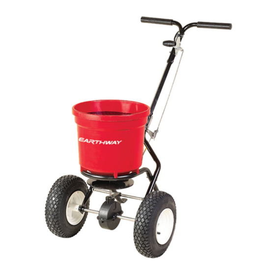
50 lb Commercial Spreader
with Side Spread Control
ASSEMBLY INSTRUCTIONS
SIDE SPREAD CONTROL
Patent U.S. 10,993,368
Your EarthWay spreader includes a patented
feature to prevent fertilizer from being spread to
the left side. To activate this feature, slide the lever below
the hopper to the back (if standing behind the spreader)
and position the left wheel 6ʺ-12ʺ from your sidewalk or
border. While activated, the spreader will not waste
fertilizer like competitor designs. Competitor deflectors
leave 7X the fertilizer inside the wheels from blocking all
the material leaving the impeller.
QTY 4
QTY 2
Philips
Screws
1 1/2" Bolts
40mm Bolts
Agitator
25mm
QTY 6 – SS M6 Locknuts
40 mm
QTY 5 – Zinc M6 Locknuts
*You may receive more hardware than is needed for this
50 mm
assembly process.
60 mm
70 mm
ROCK SALT and POWDERED MATERIALS should not be used
in this spreader as it will damage the gearbox and can void
the warranty. Use only granular materials.
ASSEMBLY HARDWARE
QTY 3
QTY 6
1 3/4" Bolts
2" Bolts
45mm Bolts
50MM Bolts
Hog Ring
Spring Clip
WARNING
QTY 2
2 1/8" Bolts
55 mm Bolts
Bushing
Bearing
PAGE 1
Advertisement
Table of Contents

Summary of Contents for EarthWay SIDESPREAD CONTROL 2150
- Page 1 ASSEMBLY INSTRUCTIONS SIDE SPREAD CONTROL Patent U.S. 10,993,368 Your EarthWay spreader includes a patented feature to prevent fertilizer from being spread to the left side. To activate this feature, slide the lever below the hopper to the back (if standing behind the spreader) and position the left wheel 6ʺ-12ʺ...
-
Page 2: Helpful Hints
50 lb Commercial Spreader with Side Spread Control MODEL # 2150 ASSEMBLY INSTRUCTIONS HELPFUL HINTS Read the directions before assembly. If your spreader does not spread evenly, be sure “FRONT” on the GEARBOX points to the front of the spreader. The impeller must turn clockwise when pushing forward. - Page 3 HOPPER bottom. The word “FRONT” on the GEARBOX must point to Front of the HOPPER. NOTE: The EarthWay logo is on the front of the hopper. Step 5: (A) Install LOWER HANDLES onto FRAME to both sides as shown.
- Page 4 50 lb Commercial Spreader with Side Spread Control MODEL # 2150 ASSEMBLY INSTRUCTIONS Step 6: Slide AXLE into the LOWER HANDLE, then the GEARBOX and into the other LOWER HANDLE as shown to the right. Next, install AXLE BEARINGS over the AXLE and into both LOWER HANDLES as shown.
- Page 5 50 lb Commercial Spreader with Side Spread Control MODEL # 2150 ASSEMBLY INSTRUCTIONS Step 9: Insert (2) 1 ¾” (45MM) bolts through the GAUGE & LEVER assembly, left UPPER HANDLE, HANDLE SHAFT, and then the right UPPER HANDLE and secure with (2) locknuts. TIGHTEN ALL HARDWARE NOW.
- Page 6 50 lb Commercial Spreader with Side Spread Control MODEL # 2150 ASSEMBLY INSTRUCTIONS Step 12: Install HANDLE SHAFT to LOWER HANDLES and PIVOT & BRACKET assembly as shown. Using (2) 2 1/8” (55MM) bolts and locknuts. TIGHTEN BOLTS AND NUTS NOW. 2 qty –...
- Page 7 50 lb Commercial Spreader with Side Spread Control MODEL # 2150 ASSEMBLY INSTRUCTIONS Step 16: Insert agitator to pinion shaft on inside of hopper. Note: the position of flat side of the agitator. This pin should be installed as shown. OPERATING INSTRUCTIONS Before filling the hopper, become familiar with the operation of this spreader.
-
Page 8: How To Order Parts
Side Spread Control MODEL # 2150 ASSEMBLY INSTRUCTIONS HOW TO ORDER PARTS Call or Email: TURF DEPOT 800-305-9255 or earthway@turfdepot.com You can find replacement Nuts and Bolts at your local hardware store. 2150 Broadcast Spreader Parts List PART #... - Page 9 50 lb Commercial Spreader with Side Spread Control MODEL # 2150 ASSEMBLY INSTRUCTIONS Broadcast Setting Matrix Calibration Techniques How to ensure your spreader is properly calibrated Make sure the drop holes in the bottom of the hopper are fully open when the Rate Control handle is on #30. If not, please adjust control cable or control rod to allow for a full open hopper position at #30.
-
Page 10: Customer Service
If a manufacturing non-conformance is found, EarthWay Products, Inc. at its discretion will repair or replace the part(s)/product at no charge provided the failure is not the result of incorrect installation, mishandling, misuse, tampering, improper storage, or normal wear and tear as determined by EarthWay.


Need help?
Do you have a question about the SIDESPREAD CONTROL 2150 and is the answer not in the manual?
Questions and answers