Table of Contents
Advertisement
Quick Links
Advertisement
Table of Contents

Related Manuals for Harman Martin P3-175


Summary of Contents for Harman Martin P3-175
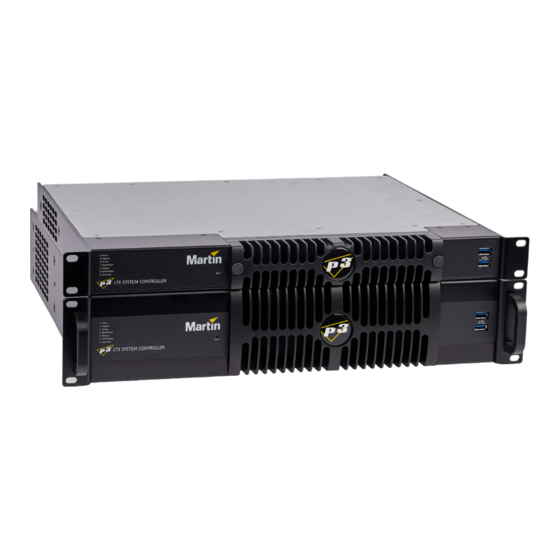
- Page 1 P3-175 and P3-275 System Controllers Quick Guide...
-
Page 2: Dimensions
©2022-2023 HARMAN PROFESSIONAL DENMARK ApS. All rights reserved. Features, specifications and appearance are subject to change without notice. HARMAN PROFESSIONAL DENMARK ApS and all affiliated companies disclaim liability for any injury, damage, direct or indirect loss, consequential or economic loss or any other loss occasioned by the use of, inability to use or reliance on the information contained in this document. -
Page 3: Table Of Contents
Contents Dimensions ............2 Safety Information . -
Page 4: Safety Information
Technical Support If you have questions about how to install or operate the fixture safely, please contact Harman Professional® Technical support: • For technical support in North America, please contact: HProTechSupportUSA@harman.com Phone: (844) 776-4899 •... - Page 5 P R O T E C T I O N F R O M F I R E • Do not modify the product in any way. • Do not operate the product if the ambient temperature (Ta) exceeds 50° C (122° F). •...
-
Page 6: Précautions D'emploi
Assistance technique Si vous avez des questions sur la façon d’installer ou d’utiliser l’appareil en toute sécurité, veuillez contacter l’Assistance technique de Harman Professional : • pour contacter l’Assistance technique en Amérique du Nord, veuillez écrire à l’adresse suivante : HProTechSupportUSA@harman.com... - Page 7 P R O T E C T I O N C O N T R E L E S R I S Q U E S D ’ I N C E N D I E • Ne modifiez l’appareil en aucun cas. •...
-
Page 8: Sicherheitshinweise
Technische Unterstützung Wenn Sie Fragen zur sicheren Installation und zum sicheren Betrieb dieses Produkts haben, wenden Sie sich bitte an den technischen Support von Harman Professional: • Nordamerika: HProTechSupportUSA@harman.com, Telefon: (844) 776-4899 • Rest der Welt: Bitte wenden Sie sich an Ihren nationalen Vertrieb. - Page 9 S C H U T Z V O R F E U E R • Verändern Sie das Produkt nicht. • Verwenden Sie das Produkt nicht bei Umgebungstemperaturen (Ta) über 50° C (122° F). • Achten Sie besonders auf ausreichende Kühlung. Der Luftstrom um die Kühlrippen darf unter keinen Umständen beeinträchtigt werden.
-
Page 10: Introduction
Thank you for selecting a product from the Martin P3 System Controllers family. Martin P3-175 and P3-275 System Controllers allow easy set up and configuration of an installation with Martin fixtures supporting the P3 protocol. The P3 System Controllers can feed the fixtures with Art-Net/sACN controls from a lighting desk, a video feed from a media server or a mix of both. -
Page 11: Physical Installation
Physical installation Rackmounting P3-175 and P3-275 System Controllers Martin Professional P3 System Controllers are designed to be rack-mounted in a central control location for fixed installations or mounted in a flightcase rack for touring applications. The enclosure and 19” rack mounting comply with IEC 60297. -
Page 12: System Installation
System installation The schematic diagrams in this section are given as examples only. For full details of installing Martin lighting and creative LED devices – including important safety information – refer to the user documentation supplied with devices and available for download free of charge from www.martin.com Example system layout –... - Page 13 Example system layout – architectural applications Figure 2 shows how a system consisting of a P3 System Controller with Martin creative LED products should be laid out and connected. Figure 2: Example system layout – architectural applications System installation...
-
Page 14: Connections: General
Connections: general To connect P3-175 and P3-275 System Controllers and prepare them for use, see the system layout diagrams on the previous pages and see later in this chapter for connections panel information depending on the controller that you want to connect. Note that you must connect the Ethernet data cable from P3-compatible fixtures to the port marked P3 OUT (on the P3-175), or one of the ports marked P3 OUT 1 and P3 OUT 2 (on the P3-275). - Page 15 P3-175 connections and status P3-175 connections panel Figure 3: P3-175 connections panel The LED at each connector on the connections panel lights up when a link is present and flashes when there is data activity on that connector. See Figure 3. The connections panels on the rear of the P3-175 offers the following features: MGMT –...
- Page 16 P3-175 front panel Figure 4: P3-175 front panel See Figure 4. The LED status indicators, Reset button and USB ports on the front panel of the P3-175 have the following functions: Active flashes during startup and lights continuously during operation. Video In indicates that the currently selected video input is valid.
- Page 17 P3-275 connections and status P3-275 connections panel Figure 5: P3-275 connections panel The LED at each connector on the connections panel lights up when a link is present and flashes when there is data activity on that connector. See Figure 5. The connections panel on the rear of the P3-275 has the following features: MGMT –...
- Page 18 P3-275 front panel Figure 6: P3-275 front panel See Figure 6. The LED status indicators and Reset button on the P3-275 front panel have the following functions: Active flashes during startup and lights continuously during operation. Video In indicates that the currently selected video input is valid. P3 Out indicates that the P3-275 is sending a P3 data signal on one or both of its P3 output ports.
-
Page 19: System Status Information
System status information You can view system status information in the P3 System Controller application. To see this information, click on the Settings button (see Figure 7) and select About from the menu. The About window shows the P3 System Controller software version, serial number, uptime (since the controller was last powered on), temperatures and more. -
Page 20: Service
Service There are no user-serviceable parts inside the P3-175 and P3-275 System Controllers. Each controller is protected against overcurrent by a thermal cutout: there is no internal fuse. Apart from the operations described below, do not open any cover or attempt to modify or repair the unit. Doing so will void the product warranty. -
Page 21: Updating And Reloading P3-175 And P3-275 System Controllers Software
4. Making sure that the filters stay in place and fully cover the air intakes, hold the fan grill up to the front of the controller and locate its four corner pins in their holes in the front of the controller. Then tighten the two thumbscrews A until the fan grill sits tightly in position. -
Page 22: Internal Battery
Internal battery P3-175 and P3-275 System Controllers have CR2032 lithium button cell battery backup to maintain real-time clock operation when the unit is not powered. Batteries should last for at least 10 years and can be replaced when necessary. If you suspect that an internal battery is no longer providing backup power, contact Martin Professional for replacement. -
Page 23: Troubleshooting
Troubleshooting Problem Probable cause(s) Remedy Check that power switch on back of controller is powered on. No power to controller. Check power and connections to controller. Controller is completely dead. Disconnect power cable. Allow device to cool. Try to reconnect and switch on the device. If the problem Thermal protection activated. - Page 24 www.martin.com...
Need help?
Do you have a question about the Martin P3-175 and is the answer not in the manual?
Questions and answers