
Related Manuals for Harman AMX NETLINX NX Series


Summary of Contents for Harman AMX NETLINX NX Series
- Page 1 H A RDW A RE REF EREN CE M A N UA L N E T LI N X N X S E R I ES I N TE G RATED C O N T RO L LE RS NX -1 20 0, N X- 220 0, N X- 320 0, N X-4 200...
- Page 2 IMPORTANT SAFETY INSTRUCTIONS READ these instructions. KEEP these instructions. HEED all warnings. FOLLOW all instructions. DO NOT use this apparatus near water. CLEAN ONLY with dry cloth. DO NOT block any ventilation openings. Install in accordance with the manufacturer's instructions. DO NOT install near any heat sources such as radiators, heat registers, stoves, or other apparatus (including amplifiers) that produce heat.
- Page 3 ESD WARNING To avoid ESD (Electrostatic Discharge) damage to sensitive components, make sure you are properly grounded before touching any internal materials. When working with any equipment manufactured with electronic devices, proper ESD grounding procedures must be followed to make sure people, products, and tools are as free of static charges as possible. Grounding straps, conductive smocks, and conductive work mats are specifically designed for this purpose.
- Page 4 Table of Contents Table of Contents Overview ......................7 Related Documents..........................7 What’s New? ........................8 Two Discrete Network Interfaces (NICs) ....................8 Using the ICSLAN Network ........................8 Automatic Binding of AMX Devices on ICSLAN..................8 Support for IPv6 Networks ........................8 Link-Local Fallback in DHCP Mode......................
-
Page 5: Table Of Contents
Table of Contents Mounting the Controller ....................21 Installing the Controller into an Equipment Rack ................21 Rack Mount Safety Instructions ......................21 Mounting the NX-1200 ......................... 22 Wiring and Connections ..................23 Overview .......................... 23 Front Panel Components....................23 Power Button ............................23 Program Port ............................ - Page 6 Table of Contents LAN 10/100 Port ..........................34 IPv4..................................35 IPv6..................................35 INPUT PWR Connector.......................... 35 Preparing Captive Wires ............................. 35 Wiring a Power Connection ..........................35 Installation of the USB Gadget Serial Driver for Windows 8.x – 32/64-Bit Operating Systems ......................37 Overview .........................
- Page 7 Overview Overview The NX-series of NetLinx Integrated Master Controllers can be programmed to control Ethernet, RS-232/422/485, Relay, IR, and Input/Output devices, as well as other AMX devices connected via AxLink, through the use of both NetLinx and Java programming languages. NetLinx programs are developed using the NetLinx Studio application version 4.x. Java programs are developed using the Cafe Duet application.
- Page 8 Overview What’s New? The following section lists the new features for the NX-series controllers. For more information about each of these items, see the What’s New for NX-Series Controllers document located on the NX controllers product pages at www.amx.com. Two Discrete Network Interfaces (NICs) The NX-2200, NX-3200 and NX-4200 controllers have two 10/100BaseT Ethernet connections.
- Page 9 Overview Copy and Clone Conf iguration On any X-Series controller, configuration information can be exported to and imported from a USB storage device. There are two different levels of configuration export: “COPY” and “CLONE”. See the NX Series NetLinx Integrated Controllers WebConsole & Programming Guide for information on using the EXPORT CONFIG and EXPORT CLONE telnet commands.
- Page 10 Overview Features The following table summarizes the features for each NX-series controller: NX-Series Controllers - Features NX-1200 NetLinx Integrated Controllers Name / FG# Features NX-1200 Controller (FG2106-01) 1 RS-232 / RS-422 / RS-485 serial port 1 RS-232-only serial port 2 IR / Serial ports 4 Digital I/O ports 1 AxLink port 1 LAN Ethernet port...
- Page 11 Overview NX-Series Controllers - Features (Cont.) NX-4200 NetLinx Integrated Controllers Name / FG# Features NX-4200 Controller (FG2106-04) 2 RS-232 / RS-422 / RS-485 serial ports 6 RS-232-only serial port 8 Relays 8 IR / Serial ports 8 Digital I/O ports 2 AxLink ports 4 ICSLAN Ethernet ports 1 LAN Ethernet port...
- Page 12 Overview NX-1200 Specif ications NX-1200 Specif ications Dimensions (HWD): 1.645" x 5.8" x 5.15" (41.78mm x 147.32mm x 130.81mm) RU: 1/3 Active Power • DC input voltage (typical): 12 V Requirements: • DC current draw: 200 mA @ 12 V •...
- Page 13 Overview NX-1200 Specif ications (Cont.) Rear Panel Components: (Cont.) RS-232 (Port 2): 1 5-pin RS-232 control port using 3.5 mm mini-Phoenix (male) connectors with XON/XOFF (transmit on/transmit off), CTS/RTS (clear to send/ready to send). Supports 300-115,200 baud. AxLink Port: 1 4-pin 3.5 mm mini-Phoenix (male) connector that provides data and power to external AxLink control devices. Green AxLink LED indicates the state of the AxLink port.
- Page 14 Overview NX-2200 Specif ications NX-2200 Specif ications Dimensions (HWD): 1.766" x 17" x 9.12" (44.85mm x 431.8mm x 231.64mm) RU: 1 Active Power • DC input voltage (typical): 12 V Requirements: • DC current draw: 250 mA @ 12 V •...
- Page 15 Overview NX-2200 Specif ications (Cont.) Rear Panel Components: (Cont.) IR/Serial 4 IR/Serial control ports support high-frequency carriers of up to 1.142 MHz with each output being capable of (Ports 11-14): two electrical formats: IR or Serial. 4 IR/Serial data signals can be generated simultaneously. IR ports support data mode (at limited baud rates and wiring distances).
- Page 16 Overview Port Numbers The following table lists the port numbers for the NX-3200: NX-3200 Port Numbers RS-232 RS-232/422/485 IR/Serial Relay 2-4, 6-8 1, 5 11-18 NX-3200 Specif ications NX-3200 Specif ications Dimensions (HWD): 1.766" x 17" x 9.12" (44.85mm x 431.8mm x 231.64mm) RU: 1 Active Power •...
- Page 17 Overview NX-3200 Specif ications (Cont.) Rear Panel Components: (Cont.) Relays (Port 21): 8-channel single-pole single-throw relay port Each relay is independently controlled. Supports up to 8 independent external relay devices Channel range = 1-8 Each relay can switch up to 24 V or 28 V @ 1 A Two 8-pin 3.5 mm mini-Phoenix (male) connectors provide connection to relays...
- Page 18 Overview NX-4200 The NX-4200 (FG2106-04) has 1GB of on-board RAM, a 13GB CompactFlash card, and is Device Discovery enabled to simplify programming by standardizing device and function definitions, default touch panel button assignments, and control and feedback methods. A complete list of device specifications is listed below. FIG.
- Page 19 Overview NX-4200 Specif ications NX-4200 Specif ications Dimensions (HWD): 1.766" x 17" x 9.18" (44.85mm x 431.8mm x 233.17mm) RU: 1 Active Power • DC input voltage (typical): 12 V Requirements: • DC current draw: 200 mA @ 12 V •...
- Page 20 Overview NX-4200 Specif ications (Cont.) Rear Panel Components: (Cont.) Relays (Port 21): 8-channel single-pole single throw relay ports Each relay is independently controlled. Supports up to 8 independent external relay devices Channel range = 1-8 Each relay can switch up to 24 V or 28 V @ 1 A Two 8-pin 3.5 mm mini-Phoenix (male) connectors provide connection to relays...
-
Page 21: Mounting The Controller
Overview Serial, IR, AxLink, and PoE Port Diagnostics When a string is sent to a serial port or an IR pulse to an IR port, the X-Series controllers can detect and report if the port being used is in a fault condition. The controllers can also detect certain fault conditions on the AxLink bus or Power-over-Ethernet (PoE) subsystem. -
Page 22: Mounting The Nx-1200
Overview Use the supplied #8-32 screws to secure the rack ears to the sides of the controller. You can attach the rack ears toward the front or rear panel for either a front-facing or rear-facing installation. Slide the unit into the rack until the attachment holes, along both sides, align to their corresponding locations on the mounting brackets, as shown in FIG. -
Page 23: Wiring And Connections
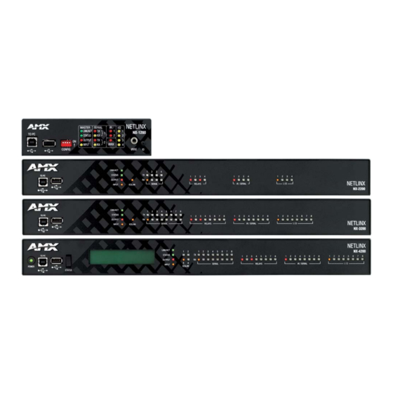
Wiring and Connections Wiring and Connections Overview This chapter provides details, specifications, wiring diagrams, and other important information for all port and connectors available on the NX-series controllers. FIG. 7 displays the NX-series controllers. NX-series controllers FIG. 7 Front Panel Components The following sections list the front panel components on the NX-series controllers. -
Page 24: Usb Port
Wiring and Connections USB Port The front panel of all models features one Type-A USB port you can use to connect a mass storage device for loading .tkn files, reading or writing configuration files and log files, or updating the firmware on the unit. NOTE: This USB port only supports a FAT32 f ile system. -
Page 25: Poe Port Status
Wiring and Connections PoE Port Status If the system is not being powered from an AC source, the status will read "PoE Not Available". Otherwise, the status consists of four subfields separated by blanks, each of the format x:cc, where x is the port number (1, 2, 3, or 4) and cc is the condition code. If there is not a fault on the port, the possible condition codes are as follows: N - No device is attached on the port or the device is not a PoE Powered Device. -
Page 26: Icslan Leds
Wiring and Connections ICSLAN LEDs The ICSLAN LEDs light green when there is an active link on the corresponding ICSLAN port. The light toggles off when a data packet is sent or received. There are 4 ICSLAN LEDs on the NX-4200. The NX-2200 and NX-3200 each have one ICSLAN LED (see FIG. 13). NX-3200/4200 NX-2200 ICSLAN LEDs... -
Page 27: Irrx Port
Wiring and Connections IRRX Port The IRRX port is a 1/8" mini-phono receiver port capable of interfacing with an IR03 External IR Receiver Module. This port is only available on the NX-1200. FIG. 19 displays the IRRX port. IRRX port FIG. -
Page 28: Rs-232/422/485 Ports
Wiring and Connections The following table lists the pinouts for the RS-232 ports. RS-232 Port Pinouts Pin 1 Pin 2 Pin 3 Pin 4 Pin 5 In the above table, pin 1 is located on the right side of the port, and the pinouts count up to the left. RS-232/422/485 Ports The RS-232/422/485 ports (ports 1 and 5 on the NX-3200/4200;... -
Page 29: Relay Ports
Wiring and Connections Relay Ports The relay ports (port 21 on the NX-2200/3200/4200) are 8-pin 3.5 mm mini-Phoenix (male) connectors used for connecting external relay devices. The NX-3200 and NX-4200 each features 2 sets of 8-pin relay connectors. The NX-2200 features one set of connectors. -
Page 30: Ir/Serial Port: Connections And Wiring
Wiring and Connections The following table list the wiring specifications for the I/O ports. In this table, pin 1 is located on the right side of the port, and the pinouts count up to the left. I/O Port Wiring Specif ications NX-3200/4200 NX-1200/2200 Signal... -
Page 31: Axlink Port And Led (4-Pin Captive-Wire)
Wiring and Connections AxLink Port and LED (4-pin captive-wire) The AxLink port allows the central controller to support AMX AxLink devices. FIG. 26 displays the AXLINK ports for each NX-series controller. NX-3200/4200 NX-2200 NX-1200 AxLink Ports and LEDs FIG. 26 The (green) AxLink LED indicates AxLink data activity: Off - No power, or the controller is not functioning properly. -
Page 32: Sdhc Card Slot
Wiring and Connections To use the 4-pin 3.5 mm mini-Phoenix (male) captive-wire connector for data communication and power transfer, the incoming PWR and GND cable from the 12 VDC-compliant power supply must be connected to the AxLink cable connector going to the central controller. -
Page 33: Icslan Ports
Wiring and Connections ICSLAN Ports The NX-2200/3200/4200 controllers have two types of Ethernet ports: LAN and ICSLAN. The LAN port is used to connect the master to an external network, and the ICSLAN ports are used to connect to other AMX equipment or third-party A/V equipment. The ICSLAN ports on all models provide Ethernet Communication to connected AMX Ethernet Equipment in a way that is isolated from the primary LAN connection. -
Page 34: Id Pushbutton
Wiring and Connections ID Pushbutton All NX-series controllers feature an ID pushbutton which you can use to toggle between static and dynamic IP addressing. You can also use the pushbutton to reset the default settings on the controller or restore the controller to its factory firmware image. FIG. -
Page 35: Ipv4
Wiring and Connections The LAN port gets its IP address(es) in one or more of the following ways: IPv4 Static assignment by the user Dynamic assignment by an IPv4 DHCP server Link local as a fall back when configured for DHCP but unable to successfully obtain address ... - Page 36 Wiring and Connections Hardware Reference Guide - NX-Series NetLinx Integrated Controllers...
-
Page 37: Installation Of The Usb Gadget Serial Driver For Windows 8.X - 32/64-Bit Operating Systems
Installation of the USB Gadget Serial Driver for Windows 8.x – 32/64-Bit Operating Systems Installation of the USB Gadget Serial Driver for Windows 8.x – 32/64-Bit Operating Systems Overview With AMX's NX-Series Controllers, the USB Gadget Serial driver must be installed differently for users running the Windows 8.X 32/64 bit Operating Systems. - Page 38 Installation of the USB Gadget Serial Driver for Windows 8.x – 32/64-Bit Operating Systems When the Control Panel opens, select the General section. (Win 8.0 users can skip to step 6.) FIG. 42 displays the PC Settings options. PC Settings FIG.
- Page 39 Installation of the USB Gadget Serial Driver for Windows 8.x – 32/64-Bit Operating Systems Once selected, you will see an Advanced startup section appear. Click on the Restart now button. FIG. 45 displays the Advanced startup page. Advanced Startup page FIG.
- Page 40 Installation of the USB Gadget Serial Driver for Windows 8.x – 32/64-Bit Operating Systems After your PC restarts, you will see a list of startup settings that you can change. Press F7 to select the "Disable driver signature enforcement" setting. FIG.
-
Page 41: Installing The Gadget Serial Driver
Installation of the USB Gadget Serial Driver for Windows 8.x – 32/64-Bit Operating Systems Installing the Gadget Serial Driver The NetLinx Studio v4.0 setup program installs the Gadget Driver into the Windows\INF directory. After completing the Disabled Driver Signature Verification procedures, use a Type-A-to-Type-B USB cable to connect your PC to the front program port on the NX controller (see FIG. -
Page 42: Manually Installing/Updating The Usb Driver
Installation of the USB Gadget Serial Driver for Windows 8.x – 32/64-Bit Operating Systems Manually Installing/Updating the USB Driver If you are still having problems with Windows 8.x finding the Gadget Serial driver files, the NetLinx Studio installer will copy a set of the driver files into the following directory: C:\Program Files (x86)\AMX Control Disc\NetLinx Studio 4\USBGadgetDriver From the Windows Control Panel, select Hardware and Sound, then select the Device Manager option. - Page 43 The AMX Warranty and Return Policy and related documents can be viewed/downloaded at www.amx.com. 3000 RESEARCH DRIVE, RICHARDSON, TX 75082 AMX.com | 800.222.0193 | 469.624.8000 | +1.469.624.7400 | fax 469.624.7153 AMX (UK) LTD, AMX by HARMAN - Unit C, Auster Road, Clifton Moor, York, YO30 4GD United Kingdom • +44 1904-343-100 • www.amx.com/eu/...
Need help?
Do you have a question about the AMX NETLINX NX Series and is the answer not in the manual?
Questions and answers