
Related Manuals for Harman AMX JPK-1300


Summary of Contents for Harman AMX JPK-1300
-
Page 1: Important Safety Instructions
HARDWARE REFERENCE MANUAL VERSION: V1.0.0 JPK-1300 Jetpack 3x1 Switching, Transport, and Control Solution UA Version EK Version AV FOR AN IT WORLD ®... - Page 2 IMPORTANT SAFETY INSTRUCTIONS READ these instructions. KEEP these instructions. HEED all warnings. FOLLOW all instructions. DO NOT use this apparatus near water. CLEAN ONLY with dry cloth. DO NOT block any ventilation openings. Install in accordance with the manufacturer’s instructions. DO NOT install near any heat sources such as radiators, heat registers, stoves, or other apparatus (including amplifiers) that produce heat.
- Page 3 ESD WARNING To avoid ESD (Electrostatic Discharge) damage to sensitive components, make sure you are properly grounded before When working with any equipment manufactured with electronic devices, proper ESD grounding procedures must be followed to make sure people, products, and tools are as free of static charges as possible. Grounding straps, conductive smocks, and conductive work mats are specifically designed for this purpose.
-
Page 4: Table Of Contents
Table of Contents Important Safety Instructions ....................2 Overview ............................6 Features ............................. 6 Package Contents ..........................6 Specifications ..........................7 Keypad Description(UA Version) ..................... 9 Wall-plate Transmitter Panel Description(UA Version) ..........10 Receiver Panel Description(UA Version) ................11 Pinout Information ........................12 RS232 ............................. -
Page 5: Overview
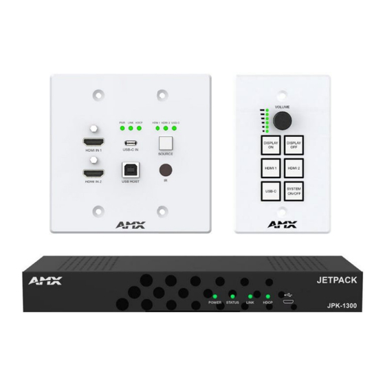
Overview The JPK-1300 is designed for multi-function AV intelligent education system. It consists of a Keypad, a Wall-plate Transmitter and an All-in-one Receiver. It offers 2 HDMI and USB Type-C video extension, video switching and system control. Uncompressed video and audio can be transmitted up to 70m/230ft at 1080P or 40m/131ft at 4K2K@30 (YUV 4:4:4) over a shielded Cat 6/6A/7 cable. -
Page 6: Specifications
Specifications Technical HDMI Compliance HDMI 2.0 HDCP Compliance HDCP 2.2 Video Bandwidth 297MHz/10.2Gbps Video Network Bandwidth Video Resolution 480i ~1080p50/60Hz, 4Kx2K@24/30Hz, 4k2k@50Hz/60Hz 4:2:0 8/10/12-bit (1080P60Hz) Color Depth 8-bit (4K30Hz 4:4:4) Color Space RGB, YCbCr 4:4:4 / 4:2:2. YUV 4:2:0 HDR, Dolby Vision, HLG IR Level 12Vp-p IR Frequency... - Page 7 Specifications General Operating 0°C to 40°C (32°F to 104°F) Temperature Storage Temperature -20°C to 60°C (-4°F to 140°F) Humidity 20% to 90%, non-condensing Human-body Model: ESD Protection ±8kV (Air-gap discharge)/±4kV (Contact discharge) Input: AC100 - 240V 50/60Hz Power Supply Output: DC 24V/3.75A (US/EU standards, CE/FCC/UL certified) Power Consumption 80W (TX + RX + Keypad) (Max)
-
Page 8: Keypad Description(Ua Version)
Keypad Description (UA Version) Name Description Use the volume knob to adjust the audio output volume of the amplifier, the corresponding volume Volume Knob and level indicator will be on. Volume Level ▪ Rotating clockwise will increase the audio volume; Indicator ▪... -
Page 9: Wall-Plate Transmitter Panel Description(Ua Version)
Wall-plate Transmitter Panel Description (UA Version) Name Description On: JPK-1300 TX is powered on. POWER LED Off: JPK-1300 TX is powered off or in standby. (Green) LED indicates the connection status of the TX and RX. On: JPK- LINK LED 1300 TX and RX are linked. -
Page 10: Receiver Panel Description(Ua Version)
Receiver Panel Description (UA Version) Name Description POWER LED On: JPK-1300 RX is powered on. (Green) Off: JPK-1300 RX is powered off or in standby. STATUS LED On: JPK-1300 RX is working properly. (Green) Blinking: JPK-1300 RX is not working properly. LED indicates the connection status of the TX and RX. -
Page 11: Pinout Information
Pinout Information The following figures show the pinouts of the Phoenix Connectors. RS232 Connects to an RS232-enabled device with the 3-pole, 3.81mm captive screw connectors. Wire as shown below: RELAY Connects to a projector screen with the 3-pole, 3.81mm captive screw connectors. Wire as shown below: Reference Manual - JPK-1300... -
Page 12: Audio Out
Audio Out Connect to an audio device with the 3-pole, 3.81mm captive screw connector. Wire as shown below: Reference Manual - JPK-1300... -
Page 13: Installation And Connection
Installation and Connection Cable Requirements CONTROL port connection distance is up to 164ft/50m via a Shielded Cat 6/6A/7 cable. The CONTROL cable must be pre- run from the Wall-plate Transmitter backbox to the Keypad backbox. AV LINK port connection distance is up to 230ft/70m for 1080P video or 131ft/40m for 4K video via a Shielded Cat 6/6A/7 cable. The AV LINK cable must be pre-run from the Receiver installation location to the Wall-plate Transmitter backbox. - Page 14 Installing Jetpack Wall-plate Transmitter and Keypad To install the UA version JPK-1300 Wall-plate TX and Keypad: Place the wall-plate TX and keypad into US standard back box. Secure the wall-plate TX and keypad with the white screws provided, as shown below. JPK-1300-UA TX JPK-1300-UA Keypad To install the EK version JPK-1300 Wall-plate TX and Keypad:...
-
Page 15: Basic Operations
Basic Operations Power on all the attached devices: When all are powered on, check all LED indicators on the JPK-1300 TX and RX to ensure the installation is successful. Use the SYSTEM ON/OFF button on the JPK-1300 Keypad to turn on/off the system. •... -
Page 16: Input Source Switching
Input Source Switching The JPK-1300 Kit supports Auto and Manual Switching between the HDMI and USB-C inputs. Auto Switching When multiple sources are inserted, and power is ON for all devices, the input will be switched to the last selected input port of the last operation. -
Page 17: Pc Tool Control
PC Tool Control Controlling the JPK-1300 through the PC tool. Download the “AMX Jetpack Manager” from amx.com and install this application tool on the PC. Before launching this tool, connect all the JPK-1300 kits and the PC into the same network. The default IP mode of JPK-1300 is DHCP. -
Page 18: Control
Set device PIN code in batches Click the checkbox at the DEVICE LIST to select at least one device, for which the PIN code is to be set. Then click “Change PIN” to pop up the “Change PIN“ window, as shown in the figure below. Enter an 8-digit PIN code in “New PIN Code”. Finally click “Set New PIN Code” to complete setting, and click “Done”... - Page 19 Click the checkbox to select the device at the DEVICE LIST, the corresponding Schedule information will be displayed on the right. Add Schedule in batches Please follow the steps below to add Schedule in batches: Step 1, Click the checkbox at the DEVICE LIST to select the device. Step 2, Click to set Auto Switching, Volume, Audio Mute, Source Inputs, Microphone/Line Gain, Display and System.
-
Page 20: Settings
Remove Schedule Click the “Remove” button in the Current Schedule list, and then click “Yes” to complete remove. Settings Export Configuration Files Click the checkbox at the DEVICE LIST to select the device. Please note that, you can only choose one device at one time. Then click “Save Config”, select the file path, and click “Confirm”... -
Page 21: Update
Update Update devices in batches Click the checkbox at the DEVICE LIST to select devices. Then click “Select Firmware File” to select the files to be updated, and click “Update All” to start batch updating. Update stages The update is divided into several stages: Stage 1. -
Page 22: Web Ui Control
Web UI Control The Web UI designed for the JPK-1300 allows basic controls and advanced settings of the device. To access the JPK-1300 Web UI: Connect your PC and the LAN port of the JPK-1300 RX to the same local area network (without router). Input the default IP address (192.168.1.2) of the JPK-1300 kit into your browser on the PC to enter Web UI. -
Page 23: Video
The Administrator Web UI page consists of six sections: Video, Audio, Control, Schedule, Network, System. Video Video Switching: Auto Switching: Click to enable/disable the Auto Switching mode. Source Inputs: Click to select the HDMI 1/HDMI 2/USB-C input signal source. Check “Video Mute” to close HDMI output, and the corresponding input channel LED on the front panel of JPK-1300 TX and Keypad will not be on. -
Page 24: Control
Audio: Volume: Move the slider to adjust the output audio volume of the AMP OUT and AUDIO OUT port on JPK-1300 RX. Check “Audio Mute” to mute audio output. Microphone/Line Gain: Move the slider to adjust the output audio volume of the MIC/LINE IN port on JPK-1300 RX. Audio Mixing Ratio (%): Move the slider to adjust the audio mixing ratio of Microphone/Line In or HDMI/USB-C/ARC-In (Ratio range: 0~100%). - Page 25 Relay Settings: Screen Up/Down: Click “Up” to trigger Relay 1 open/closed; Click “Down” to trigger Relay 2 open/closed. Relay Normal State: Click to select the Relay state (Normally Open/Normally Closed). Relay Port Assignment: Click to select Screen Up/Screen Down for Relay 1 and Relay 2 respectively. Relay Mode: Click to select Momentary (To be open/closed briefly) or Latch (To be open/closed for a long time).
-
Page 26: Schedule
Schedule The Schedule page is used to make presets. For example, for the preset of JPK-1300 POWER ON function, set parameters as shown in the above figure: Select Disable for Auto Switching, set the Volume to 8, set Microphone/Line GAIN to 0, select “HDMI 1” as the input source, set Display and System to “ON”;... -
Page 27: Network
Network The Network page is used to respectively make IPV4/ IPV6/802.1x Network Settings for the System, as shown in the figures below. After setting, press the “Accept” button to save changes, or press the “Reset” button to revert values from the System. Reference Manual - JPK-1300... -
Page 28: System
System General Settings: Label Setting: Set the Web Label name. Keypad Setting: Move the slider to adjust the Keypad backlight brightness (Range: 0~100). Data and Time Setting: Set the data and time for the system. Firmware Version: Display the software versions of JPK-1300 RX/TX/Keypad/Web. Firmware Update: Click "Load File"... - Page 29 Security Settings: The Security section is used for Network security settings. Reference Manual - JPK-1300...
-
Page 30: Firmware Upgrade
Firmware Upgrade JPK-1300 supports upgrade the firmware through the PC tool and Web UI control. Before Starting Verify that you have the latest version of PC tool and Web UI on your PC. Download the latest firmware file to your PC. (Place firmware files on a local drive for the fastest throughput.) Verify the following: a) Verify that an Ethernet/RJ-45 cable is connected from the JPK-1300 RX to the same network as the control system. - Page 31 Please follow the steps below to upgrade the firmware through the Web UI control: Step 1. Login the Web UI and select the General page of the System tab. Step 2. Click “Load File” in “Firmware Update” to load the firmware file to be upgraded, and then click “Apply” to start upgrading. Note: Do not power off the device until it has been successfully upgraded.
-
Page 32: Troubleshooting
Troubleshooting Power: Ensure all devices are powered on. Indicator: Ensure all LED indicators of the JPK-1300 are normal according to the Hardware Reference Manual. Devices: Ensure picture can be shown normally when directly connecting a source a display device. Cable: Plug the HDMI/Cat X cable in and out or connect a different HDMI/Cat X cable. Ensure the specific cable length is within the available transmission range according to the Specifications Section. -
Page 33: Api Command Set
API Command Set The API Command list support sent by TCP/IP interface (Telnet ans SSH) and by Serial port for JPK-1300 Kit Command Format Notes: In the Command Example sections of this document, <CR> indicates a carriage return as defined by your control method (e.g., \ x0d, $0d, 00x0d, 0x0d, 0dH). -
Page 34: System Commands
System Commands Command Function Description Example >help<CR> ----------------- Help ------------------------------- (Extended diag messages are OFF) ---System Commands--- ? Or help This list Display the commands listed in the ? Or help ping pint to specified ip address fwversion table Request the firmware vesrion of the device ---Network Commands--- >?set vidin hdcp<CR>... - Page 35 System Commands Command Function Description Example >set serial on<CR> Serial port is set to on > set serial <on | off> >set serial off<CR> Set serial port on or off --Notice: Serial port cannot response to serial Default Value: command when serial off.-- Would you like to set serial port to off? Y/N ->y<CR>...
- Page 36 System Commands Command Function Description Example get ntp >get ntp<CR> Get ntp server setting --Current ntp server: us.pool.ntp.org Default Value: > us.pool.ntp.org >set ntp<CR> Please input ntp server: set ntp current ntp server: us.pool.ntp.org New Set ntp server ntp server: asia.pool.ntp.org<CR> Default Value: Would you like to save this setting(Y/N) y<CR>...
-
Page 37: Network Commands
Network Commands Command Function Description Example get friendly Variables: friendly name = maxmum >get friendly<CR> 20 digitial length Get device’s IP hostname --Current device friendly name: JPK-1300-0050425 > Default Value: model with last 7 digits of serial # in Capital Letters (e.g. - Page 38 Network Commands Command Function Description Example get dns Variables: dns1 >get dns dns2 DNS Servers dns3 ------------------------------------------ Domain suffix: amx.com Get device’s DNS address Default Value: Entry 1: 192.168.1.1 Entry 2: 192.168.1.1 Domain Name: amx.com Entry 3: 192.168.1.1 DNS1(for static >...
-
Page 39: Security Commands
Security Commands Command Function Description Example Sets the device’s IP port listened to >set telnet port<CR> set telnet port for Telnet connections. Current telnet port number = 23 Variables: Enter new telnet port number(0 = disable telnet) NOTE: This command requires a ->25<CR>... -
Page 40: Video And Audio Commands (Direct Control)
Video and Audio Commands (Direct Control) Command Function Description Example get auto switch mode Command: Variables: get auto switch mode Get auto switch mode state for video <state> = enable | disable output Return: Default Value: get auto switch mode enable enable set auto switch mode:<state>... - Page 41 Video and Audio Commands (Direct Control) Command Function Description Example Command: get vidin edidmode get vidin edidmode Get edid mode for the device Default Value: input Return: auto get device input edid mode set to auto set vidin edidmode:<edid_ mode> Variables: <edid_mode>...
- Page 42 Video and Audio Commands (Direct Control) Command Function Description Example Command: get ediddata:native Return: get native ediddata is: 00 FF FF FF FF FF FF 00 05 B8 00 11 04 00 00 00 1C 19 01 03 80 00 00 78 0E EE get ediddata:<edid_ 95 A3 54 4C 99 26 0F 50 54 FF FF 80 D1 00 B3 00 A9 channel>...
- Page 43 Video and Audio Commands (Direct Control) Command Function Description Example set vidout hdcp:<hdcp_ mode> Variables: <hdcp_mode> = Command: { AUTO set vidout hdcp:hdcp2.2 Set HDCP mode for output HDCP2.2 HDCP1.4 NO-HDCP Return: output is set to HDCP2.2 mode Default Value: auto get vidout mute Command:...
- Page 44 Video and Audio Commands (Direct Control) Command Function Description Example get audout mute Command: Variables: get audout mute <state>= on | off Get audio mute state Return: Default Value: get audio mute set to off for output set audout mute:<state> Command: Variables: set audout mute:on...
- Page 45 Video and Audio Commands (Direct Control) Command Function Description Example get audin mic mix Command: Variables: get audin mic mix <ratio>= 0 ~ 100 Get micphone audio in mix ratio Return: Default Value: get micphone audio mix ratio 60 set audin mic mix:<ratio> Command: Variables: set audin mic mix:60...
-
Page 46: Control Commands (Direct Control)
Control Commands (Direct Control) Command Function Description Example get serial cmd format Variables: <format>= ASCII | HEX <end_flag>= none Command: (for \r, Line Feed) get serial cmd format (for \n, Carriage Get serial command format Return: Return) get serial command format to be ascii and end with LF (for \r\n, Line Feed and Carriage Return) Default Value:... - Page 47 Control Commands (Direct Control) Command Function Description Example Command: get serial disp off cmd Get serial control display off get serial disp off cmd Return: commands get serial display control off command:POWER OFF, delay 100ms, none set serial disp off cmd:<cmd1>,<delay_ time>,<cmd2>...
- Page 48 Control Commands (Direct Control) Command Function Description Example Command: get ir disp on cmd get ir disp on cmd Return: get ir display control on command:0000 006c 0022 0002 Variables: 0156 00ac 0015 0015 0016 0015 0016 0015 <cmd_content>= 0015 0015 0016 0040 0015 0015 0016 0040 0015 Get ir control display on 0015 0016 0040 0015 0040 0016 0040 0016 0040 none (for clear saved...
- Page 49 Control Commands (Direct Control) Command Function Description Example get ir disp off delay Command: Variables: Get ir control display off delay get ir disp off delay <time>= 0 ~ 60 s time Return: Default Value: get ir control display off delay 30s set ir disp off delay:<time>...
- Page 50 Control Commands (Direct Control) Command Function Description Example set relay normal state:<relay_state> Variables: Command: <relay_state>= set relay normal state:closed Set relay normal state open Return: closed set relay 1 and relay 2 normal state closed Default Value: open get relay momentary time Command: Variables: get relay momentary time...
- Page 51 Control Commands (Direct Control) Command Function Description Example set relay disp off delay:<time> Command: Variables: Set relay control display off set relay disp off delay:60 <time>= 0 ~ 300 s delay time Return: set relay control display off delay 60s Default Value: 30 s set relay disp...
- Page 52 Control Commands (Direct Control) Command Function Description Example Command: set display:<state> set disp manual:on set display on/off Variables: Return: <state>= on | off set display manual on get auto display Command: Variables: get auto display <state>= enable | disable get auto display control state Return: Default Value: get auto display enable...
-
Page 53: Schedule Commands (Direct Control)
Schedule Commands (Direct Control) Command Function Description Example get time Variables: <hour> = 0~23 Command: <minute> = 0~59 get time <second> = 0~59 Get the current time in Device Return: Default Value: get the current time is 11:30:40 hour = 0 minute = 0 second = 0 set time:<hour>,<minute>,... - Page 54 Command Function Description Example set schedule:<event#>, <action>,<start_time>, <repeat_pattern>,<repeat_ start>, <repeat_end>, <action_name> Variables: <event#> = 1 ~10 (maximum 10 events) <action> = (can be one or more of below settings) auto switch enable | disable (= set auto switch mode:<state>) switch hdmi1 | hdmi2 | usbc (= set switch CI) video mute: on | off (= set vidout mute) display on |...
- Page 55 © 2023 Harman. All rights reserved. SmartScale, NetLinx, Enova, AMX, AV FOR AN IT WORLD, and HARMAN, and their respective logos are registered trademarks of HARMAN. Oracle, Java and any other company or brand name referenced may be trademarks/registered trademarks of their respective companies.
Need help?
Do you have a question about the AMX JPK-1300 and is the answer not in the manual?
Questions and answers