Table of Contents
Advertisement
Quick Links
Advertisement
Table of Contents

Subscribe to Our Youtube Channel
Related Manuals for Harman JBL PROFESSIONAL INTONATO 24


Summary of Contents for Harman JBL PROFESSIONAL INTONATO 24
- Page 1 INTONATO Monitor Management T uning System Operation Manual...
-
Page 2: Table Of Contents
Table of Contents Introduction ����������������������������������������������������������������������1 Configuring the Clock Source ��������������������������������������76 Clocking via the Internal Clock ��������������������������������������������������77 Features ����������������������������������������������������������������������������3 Clocking via AES ����������������������������������������������������������������������78 Clocking via Word Clock ����������������������������������������������������������79 Front Panel Overview ������������������������������������������������������4 Using BLU link ����������������������������������������������������������������80 Rear Panel Overview �������������������������������������������������������6 BLU link Specifications �������������������������������������������������������������80 Making BLU link Connections ���������������������������������������������������80 Installing the Intonato 24 �������������������������������������������������9 BLU link Mastership �����������������������������������������������������������������81... -
Page 3: Introduction
Introduction Introduction Thank you for purchasing the JBL Intonato 24 Monitor Management Tuning System. The Intonato ® 24 is a powerful, sophisticated speaker management processor and monitor controller for audio recording, post production, and broadcast facilities. With support for mono to immersive surround formats, the Intonato 24 provides the centerpiece for a scalable audio production monitoring system. - Page 4 Introduction For the studio engineer, the Intonato 24 provides master mute, dim, and monitor volume control, as well as individual speaker mute/solo control, and monitor SPL indication. Integrated Auto-Calibration System The Intonato 24 includes a sophisticated auto-calibration system that leverages JBL’s decades of experience integrating speaker systems into real-world production environments.
-
Page 5: Features
Features Features • Support for 44.1, 48, 88.2, and 96 kHz sample rates • Up to 24 simultaneous inputs from the available 24 analog, 24 AES, and 24 BLU link input channels • Up to 24 analog and BLU link output channels •... -
Page 6: Front Panel Overview
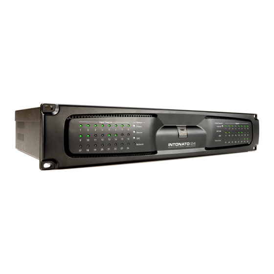
Front Panel Overview Front Panel Overview 1. Input Source LEDs These LEDs indicate input signal status of the 24 configured inputs post the A/D converters (if analog) and before the DSP. Signal status is indicated as follows: • LED Off –... - Page 7 Front Panel Overview 4. Output LEDs These 24 output LEDs indicate output signal status post the DSP. Signal status is indicated as follows: • – The output channel is not configured for use in the current scene. LED Off • –...
-
Page 8: Rear Panel Overview
Rear Panel Overview Rear Panel Overview IP: 169.254.30.21 Events: HQ: 2:6:801B SYSTEM BOOT 10 11 12 13 1. Power Switch This rocker-type power switch is used to turn the Intonato 24’s power on or off. 2. Microphone Input Connector This balanced female XLR input serves two purposes: connect the included measurement microphone to initially calibrate the speaker system to the monitoring environment;... - Page 9 Rear Panel Overview Each analog D-Sub input connector has an accompanying Ground Lift button. If hum occurs at an input, and is due to a ground loop between the Intonato 24 and the connected source device, engaging the associated Ground Lift button will break the ground loop. •...
- Page 10 Rear Panel Overview 12. Word Clock Input In cases where an external master (or “house”) clock is used for reference, connect the word clock output of the master clock device to this BNC connector. See “Configuring the Clock Source” on page 76 for information on using word clock.
-
Page 11: Installing The Intonato 24
Installing the Intonato 24 Installing the Intonato 24 IMPORTANT: Read the important safety instructions included in the box before installing and operating this product. Rack Installation THE INTONATO 24 IS FOR RACK MOUNT USE ONLY. Install the Intonato 24 in a 19” rack with the provided rack screws and washers. -
Page 12: Installing The Jbl Intonato Control App
Installing the JBL Intonato Control App Installing the JBL Intonato Control App The free JBL Intonato control app is used to program and control the Intonato 24. It is available for compatible Android, iOS, Mac, and Windows devices. Device Requirements Visit http://www.jblpro.com/intonato24 for the latest information on device requirements for the JBL... -
Page 13: Connecting To The Network
Connecting to the Network Connecting to the Network Connecting to a Wired Network Switch or Router Wired Network Switch Connection NOTE: The Intonato 24 must be connected to a DHCP-enabled network for initial configuration and control. Intonato 24 Intonato 24 1. -
Page 14: Connecting To A Wi-Fi Network Router
Connecting to the Network Connecting to a Wi-Fi Network Router Wi-Fi Network Router Connection NOTE: The Intonato 24 must be connected to a DHCP-enabled network for initial configuration and control. Intonato 24 Intonato 24 1. Connect a Cat5, Cat5e, or Cat6 Ethernet IP: 169.254.30.21 IP: 169.254.30.21 Events:... -
Page 15: Using The Intonato 24 Control App
Using the Intonato 24 Control App Using the Intonato 24 Control App The Intonato 24 is configured using the JBL Intonato control app. For information on downloading and installing the JBL Intonato control app, see “Installing the JBL Intonato Control App” on page 10 . The following sections describe, in order, how to configure and use the Intonato 24 processor. -
Page 16: Selecting The Speaker Layout Type �������������������������������������������14 Configuring The Network Using Netsetter
Using the Intonato 24 Control App Selecting the Speaker Layout Type The first step in configuring the Intonato 24 is to select the speaker layout that suits the application: 1. When connecting to the Intonato 24 for the first time, the control app will automatically navigate to the Speaker Layout screen. -
Page 17: About Speaker Layouts, Profiles, And Scenes
Using the Intonato 24 Control App About Speaker Layouts, Profiles, and Scenes Profiles and scenes are stored to the speaker layout type selected during configuration. Up to 30 profiles can be stored to each of the six speaker layout types, and up to 30 scenes can be stored to each of the 30 profiles (see illustration below). -
Page 18: About The Aux Outputs
Using the Intonato 24 Control App About the Aux Outputs When speaker layout 2, 4, or 6 is selected, Intonato 24 output channels 23 and 24 are configured to provide a stereo auxiliary feed, which can be connected to an external headphone amplifier for recording sessions (for example, during voiceover or ADR recording sessions in an editing facility where a mixing console is not available). -
Page 19: Configuring Inputs
Using the Intonato 24 Control App Configuring Inputs Once the speaker layout type has been selected, it’s time to configure the inputs for the application. The inputs can be configured by selecting Edit Settings from the Main User Menu. The Input Configuration screen is the first screen displayed from this menu. - Page 20 Using the Intonato 24 Control App input channel will be routed through the LFE low-pass filter and on to the subwoofer outputs. Any number of inputs can be designated as LFE input channels. NOTE: Ensure subwoofers are set to LFE mode, if applicable. NOTE: The LFE signal level must also be set in the Scene Builder screen to feed the LFE input signal to the subwoofer(s).
-
Page 21: Configuring Outputs
Using the Intonato 24 Control App Configuring Outputs The next step is to configure the Intonato 24 outputs. The Output Configuration screen can be accessed by selecting Edit Settings from the Main User Menu, then going to the second screen by swiping or selecting the second bubble at the bottom. - Page 22 Using the Intonato 24 Control App Bass Management (Sub1, Sub2, etc.) Checking a checkbox in this column will configure the channel to be bass managed to the assigned subwoofer whenever the master Bass Management button is enabled. When bass management is enabled, a crossover will be applied to split the signal between the satellite and subwoofer speakers.
-
Page 23: Configuring Utility Settings ��������������������������������������������������������21 Specifications
Using the Intonato 24 Control App Configuring Utility Settings The next step is to configure the Intonato 24 utility settings. The Utility screen can be accessed by selecting Edit Settings from the Main User Menu, then going to the fourth screen by swiping or selecting the fourth bubble at the bottom. - Page 24 Using the Intonato 24 Control App NOTE: When using BLU link, all devices on the BLU link bus must be configured with the same sample rate setting. AES Input C SRC Enable This dropdown menu turns sample rate conversion on AES Input C on or off. When enabled, the SRC LED on the front panel will light.
-
Page 25: Configuring Blu Link Outputs
Using the Intonato 24 Control App Configuring BLU link Outputs If the application requires BLU link output from the Intonato 24, BLU link output settings should be configured next by selecting BLU Link Output from the Main User Menu. From the BLU Link Output screen, up to 24 BLU link channels can be assigned to the BLU link bus. To assign BLU link output channels, select the BLU link output channel to assign then enable the Status button for each. -
Page 26: Calibrating The System
Using the Intonato 24 Control App Calibrating the System Once configuration is complete, the next step is to run the auto-calibration process. When used in conjunction with the included measurement microphone, a monitoring system can be automatically calibrated to the production environment. The auto-calibration process starts by detecting level differences between speakers in the system and adjusting levels to match. -
Page 27: User Eq Refinement Recommendations
Using the Intonato 24 Control App User EQ Refinement Recommendations Low Frequencies After performing auto calibration, we recommend evaluating the low-frequency performance of the system by listening to material with which you are familiar. While the system is designed to deliver flat low-frequency response in the room, different room sizes require differing compensation. - Page 28 Using the Intonato 24 Control App Balancing Subwoofers – Bass Management and LFE Levels When using bass management and LFE channels, it’s important to balance the levels between the two properly. Up to four subwoofers may be used for bass management—extending the low- frequency response of the speaker system.
- Page 29 Using the Intonato 24 Control App 3. Next, play some source material that includes LFE signal, and ensure the LFE signal is passing through the system. Select Edit Settings from the Main User Menu, then adjust the Input Trim control of the LFE channel to produce the desired SPL in the room. Repeat for any additional source LFE channels.
-
Page 30: The System Calibration Screen
Using the Intonato 24 Control App The System Calibration Screen From the System Calibration screen, individual speaker levels, time-of arrival delay offsets, and room EQ can be automatically calibrated and/or manually adjusted for the monitoring environment. To access the System Calibration screen, select System Calibration from the Main User Menu. Channel Selection (Leftmost Column) This column allows an output channel to be selected for editing. - Page 31 Using the Intonato 24 Control App Band 1–12 Buttons These buttons select one of twelve bands for editing. Type Dropdown Menu This dropdown menu selects the type of filter for the selected band, with bell, low shelf, high shelf, lowpass, and highpass filters available for each band. Copy Band and Paste Band Buttons These buttons can be used to copy the settings of a single band and paste them to a band of another speaker output channel.
- Page 32 Using the Intonato 24 Control App The Signal Generator Screen The Intonato 24’s built-in signal generator can produce sine wave tones, pink noise, or white noise that can be fed to any or all output channels (with the exception of the aux outputs). The Intonato 24 also provides a SPL readout to visually indicate monitoring level, which must be calibrated once setup is complete.
- Page 33 Using the Intonato 24 Control App SPL Calibration Instructions Follow these instructions to calibrate the SPL readout. Measured SPL Readout This readout displays the measured sound pressure level. Follow the on-screen SPL calibration instructions to calibrate this value. User Calibration Offset Slider Adjust this slider to calibrate the SPL readout.
-
Page 34: Adjusting User
Using the Intonato 24 Control App Adjusting User EQ After the system has been calibrated, the User EQ can be used to make refinements to the system’s frequency response, without affecting the calibrated Room EQ settings. This includes calibrating the monitor system to the X Curve or another custom frequency-response contour. - Page 35 Using the Intonato 24 Control App Gain Slider This parameter adjusts the gain of the selected band. Q Slider This parameter adjusts the width of the selected band. Show/Hide TouchPoint Button This button toggles visibility of the band-numbered touchpoints in the graph. Band 1–8 Buttons These buttons select one of eight bands for editing.
-
Page 36: Using Profiles
Using the Intonato 24 Control App Using Profiles Profiles contain settings configured for a given type of session and can be managed from the Store/ Recall screen. Up to 30 profiles can be stored in the Intonato 24 (per speaker layout), and profiles can be backed up to the control device’s file system. - Page 37 Using the Intonato 24 Control App Recall Button This button recalls a profile from within the Intonato 24 device. To recall a profile, select the desired profile from the device profile list, then press the Recall button. Rename Button This button opens a naming screen, where the selected profile can be renamed in the Intonato 24 device.
-
Page 38: Creating Scenes
Using the Intonato 24 Control App Creating Scenes The Scene Builder is used to create scenes during configuration. Scenes allow the studio engineer to switch between different sources to monitor, select alternate speaker systems for reference monitoring, and monitor downmixed versions of surround mixing formats. Some preconfigured scenes come packaged in the app to get you started. - Page 39 Using the Intonato 24 Control App The images below show a typical 5.1 system and an example of how the Scene Builder settings might be set for the first scene. You can see that the “mix” source (the main mix from the mixer or DAW) is IP: 169.254.30.21 Events: HQ: 2:6:801B SYSTEM BOOT...
-
Page 40: Setting The Security Password And Updating Firmware
Using the Intonato 24 Control App Setting the Security Password and Updating Firmware After the Intonato 24 has been configured for the application, a master password can be set to prevent unauthorized configuration changes. This password can be set from the Settings screen, which can be accessed by selecting Settings from the Main User Menu. -
Page 41: The Desktop Controller Screens
Using the Intonato 24 Control App The Desktop Controller Screens The Desktop Controller screens can be accessed by selecting Desktop Controller from the Main User Menu. From this screen, any Intonato DC desktop controllers connected to the network are listed and can be paired to an Intonato 24 for control. See the Intonato DC manual for more information on the Desktop Controller screens and pairing an Intonato DC for intonato 24 control. -
Page 42: User Control - Master Controls
Using the Intonato 24 Control App User Control – Master Controls The first user control screen (or Mute/Solo screen) can be accessed by selecting Controls from the Main User Menu. From this screen, the studio engineer can see input/output status, solo and mute individual speakers, turn bass management on or off, activate the talkback mic, and control master volume, mute, and dim. - Page 43 Using the Intonato 24 Control App Settings Button Opens the Settings screen, where the reset level and dim level can be calibrated by the studio engineer. The Reset Level parameter sets the level that the Master Volume control will be reset to when pressing the Reset button. The Dim Level parameter sets how much the signal level will be attenuated when the studio engineer presses the Dim button.
- Page 44 Using the Intonato 24 Control App Mute Button Pressing this master button will mute the monitored signal in all output channels configured for master volume control. NOTE: The state of the Mute button is not affected when a new profile or scene is recalled. Talkback Button This button is only available if the aux outputs are active—meaning speaker layout 2, 4, or 6 has been selected.
-
Page 45: User Control - Recalling Scenes
Using the Intonato 24 Control App User Control – Recalling Scenes The second user control screen (or Recall Scene screen) can be accessed by selecting Controls from the Main User Menu, then swiping or selecting the second bubble at the bottom. From here, the studio engineer can recall different pre-programmed scenes. -
Page 46: Application Examples
Application Examples Application Examples 2.1 Bi-Amplified Application From Sources Speaker Amps Speaker Amps 1. Mix L 1. L High 1. L 2 2. Mix R 2. L Low 2. R 2 3. Cue Mix L 3. R High 3. M 4. - Page 47 Application Examples 2.1 Bi-Amplified Application Notes – Speaker Layout Configuration: • Speaker layout 4 has been selected for this application. This provides up to 3 bi-amplified outputs, 14 full-range outputs, and 2 subwoofer outputs. The 2-channel aux output carries the mix and talkback mic signal and is fed to the talent’s headphone amplifier.
- Page 48 Application Examples 2.1 Bi-Amplified Application Notes – Input Configuration: • The screenshot below shows the Input Configuration screen for this application. From this screen, physical inputs are assigned, input group assignments are made (to color-code input channels), inputs are named, and input trims are calibrated if required. NOTE: When the talkback mic is configured, it will be routed to input channel 24.
- Page 49 Application Examples 2.1 Bi-Amplified Application Notes – Output Configuration: • The screenshot below shows the Output Configuration screen for this application. From this screen, speaker group assignments are made (to color-code the output channels), outputs are named, speaker tunings are selected (if available), outputs are assigned for bass management, and outputs are assigned to be controlled by the master volume, mute, and dim controls.
- Page 50 Application Examples 2.1 Bi-Amplified Application Notes – Utility Configuration: • The screenshot below shows the Utility screen for this application. From this screen, the bass management crossover frequency can be fine-tuned and additional settings configured for the application. • For more information on the fields shown in this screen, see “Configuring Utility Settings” on page 21 .
- Page 51 Application Examples 2.1 Bi-Amplified Application Notes – Scene Configuration: • The screenshot below shows the Scene Builder screen for this application, where scenes are created. In this application, scenes are used to select the CD player source for reference and select the stereo or mono nearfield speakers for monitoring.
- Page 52 Application Examples 2.1 Bi-Amplified Application Notes – User Master Control: • The screenshot below shows the first user control screen for this application. From this screen, the engineer can mute and solo individual speakers, turn bass management on or off, and control master volume, mute, and dim.
- Page 53 Application Examples 2.1 Bi-Amplified Application Notes – User Scene Selection: • The screenshot below shows the second user control screen for this application. From here, the engineer can recall scenes that select sources or speaker systems for monitoring, or select alternate downmixing options.
-
Page 54: 5�1 Full-Range Application
Application Examples 5.1 Full-Range Application From From Sources Speaker Amps Sources Speaker Amps 1. Blu-ray Lf 1. Mix Lf 1. Lf 1. Not Used 2. Blu-ray Rf 2. Mix Rf 2. Rf 2. Not Used 3. Blu-ray C 3. Mix C 3. - Page 55 Application Examples 5.1 Full-Range Application Notes – Speaker Layout Configuration: • Speaker layout 2 has been selected for this application. This provides up to 20 full-range outputs and 2 subwoofer outputs. The 2-channel aux output carries the fold-down mix and talkback mic signal and is fed to the talent’s headphone amplifier.
- Page 56 Application Examples 5.1 Full-Range Application Notes – Input Configuration: • The screenshot below shows the Input Configuration screen for this application. From this screen, physical inputs are assigned, input group assignments are made (to color-code input channels), inputs are named, input LFE channels are designated, and input trims are calibrated if required. NOTE: When the talkback mic is configured, it will be routed to input channel 24.
- Page 57 Application Examples 5.1 Full-Range Application Notes – Output Configuration: • The screenshot below shows the Output Configuration screen for this application. From this screen, speaker group assignments are made (to color-code the output channels), outputs are named, speaker tunings are selected (if available), outputs are assigned for bass management, and outputs are assigned to be controlled by the master volume, mute, and dim controls.
- Page 58 Application Examples 5.1 Full-Range Application Notes – Utility Configuration: • The screenshot below shows the Utility screen for this application. The bass management crossover frequency and LFE low-pass filter frequency can be fine-tuned from this screen. Delays for the speaker system and talent headphones (to compensate for video display latency and restore “lip synchronization”) and additional settings can also be configured from here.
- Page 59 Application Examples 5.1 Full-Range Application Notes – Scene Configuration: • The screenshot below shows the Scene Builder screen for this application, where scenes are created. In this application, scenes are used to select the Blu-ray™/DVD player source for reference and select the stereo or mono nearfield speakers for monitoring.
- Page 60 Application Examples 5.1 Full-Range Application Notes – User Master Control: • The screenshot below shows the first user control screen for this application. From this screen, the engineer can mute and solo individual speakers, turn bass management on or off, and control master volume, mute, and dim.
- Page 61 Application Examples 5.1 Full-Range Application Notes – User Scene Selection: • The screenshot below shows the second user control screen for this application. From here, the engineer can recall scenes that select sources or speaker systems for monitoring, or select alternate downmixing options.
-
Page 62: 7�2 Bi-Amplified Application
Application Examples 7.2 Bi-Amplified Application From From Sources Speaker Amps Sources Speaker Amps Speaker Amps 1. Blu-ray Lf 1. Mix Lf 1. Lf High 1. Rs High 1. R High 2. Blu-ray Rf 2. Mix Rf 2. Lf Low 2. Rs Low 2. - Page 63 Application Examples 7.2 Bi-Amplified Application Notes – Speaker Layout Configuration: • Speaker layout 6 has been selected for this application. This provides up to 10 bi-amplified outputs and 2 subwoofer outputs. The 2-channel aux output carries the fold-down mix and talkback mic signal and is fed to the talent’s headphone amplifier.
- Page 64 Application Examples 7.2 Bi-Amplified Application Notes – Input Configuration: • The screenshot below shows the Input Configuration screen for this application. From this screen, physical inputs are assigned, input group assignments are made (to color-code input channels), inputs are named, input LFE channels are designated, and input trims are calibrated if required. NOTE: When the talkback mic is configured, it will be routed to input channel 24.
- Page 65 Application Examples 7.2 Bi-Amplified Application Notes – Output Configuration: • The screenshot below shows the Output Configuration screen for this application. From this screen, speaker group assignments are made (to color-code the output channels), outputs are named, speaker tunings are selected (if available), outputs are assigned for bass management, and outputs are assigned to be controlled by the master volume, mute, and dim controls.
- Page 66 Application Examples 7.2 Bi-Amplified Application Notes – Utility Configuration: • The screenshot below shows the Utility screen for this application. The bass management crossover frequency and LFE low-pass filter frequency can be fine-tuned from this screen. Delays for the speaker system and talent headphones (to compensate for video display latency and restore “lip synchronization”) and additional settings can also be configured from here.
- Page 67 Application Examples 7.2 Bi-Amplified Application Notes – Scene Configuration: • The screenshot below shows the Scene Builder screen for this application, where scenes are created. In this application, scenes are used to select the Blu-ray/DVD player source for reference and select the stereo nearfield speakers for monitoring.
- Page 68 Application Examples 7.2 Bi-Amplified Application Notes – User Master Control: • The screenshot below shows the first user control screen for this application. From this screen, the engineer can mute and solo individual speakers, turn bass management on or off, and control master volume, mute, and dim.
- Page 69 Application Examples 7.2 Bi-Amplified Application Notes – User Scene Selection: • The screenshot below shows the second user control screen for this application. From here, the engineer can recall scenes that select sources or speaker systems for monitoring, or select alternate downmixing options.
-
Page 70: Dolby Atmos Application
Application Examples Dolby Atmos Application From From From Sources Speaker Amps Sources Speaker Amps Sources Speaker Amps 1. Mix LsS 1. Blu-ray C 1. Mix Lf 1. Lf 1. RsS 1. Not Used 2. Mix RsS 2. Blu-ray LFE 2. Mix Rf 2. - Page 71 Application Examples Dolby Atmos Application Notes – Speaker Layout Configuration: • Speaker layout 1 has been selected for this application. This provides up to 20 full-range outputs and 4 subwoofer outputs. Speaker Layout Selection Screen INTONATO Operation Manual Page 69...
- Page 72 Application Examples Dolby Atmos Application Notes – Input Configuration: • The screenshot below shows the Input Configuration screen for this application. From this screen, physical inputs are assigned, input group assignments are made (to color-code input channels), inputs are named, input LFE channels are designated, and input trims are calibrated if required. •...
- Page 73 Application Examples Dolby Atmos Application Notes – Output Configuration: • The screenshot below shows the Output Configuration screen for this application. From this screen, speaker group assignments are made (to color-code the output channels), outputs are named, speaker tunings are selected (if available), outputs are assigned for bass management, and outputs are assigned to be controlled by the master volume, mute, and dim controls.
- Page 74 Application Examples Dolby Atmos Application Notes – Utility Configuration: • The screenshot below shows the Utility screen for this application. The bass management crossover frequency and LFE low-pass filter frequency can be fine-tuned from this screen. Delays for the speaker system and talent headphones (to compensate for video display latency and restore “lip synchronization”) and additional settings can also be configured from here.
- Page 75 Application Examples Dolby Atmos Application Notes – Scene Configuration: • The screenshot below shows the Scene Builder screen for this application, where scenes are created. In this application, scenes are used to select the Blu-ray/DVD player source for reference. • Downmixing options are customizable to suit the application.
- Page 76 Application Examples Dolby Atmos Application Notes – User Master Control: • The screenshot below shows the first user control screen for this application. From this screen, the engineer can mute and solo individual speakers, turn bass management on or off, and control master volume, mute, and dim.
- Page 77 Application Examples Dolby Atmos Application Notes – User Scene Selection: • The screenshot below shows the second user control screen for this application. From here, the engineer can recall scenes that select sources or speaker systems for monitoring, or select alternate downmixing options.
-
Page 78: Configuring The Clock Source
Configuring the Clock Source Configuring the Clock Source The Intonato 24 can be clocked via the internal crystal oscillator, AES input, Word Clock input, or BLU link bus. To use BLU link, a 48 or 96 kHz sample rate must be used. In order for BLU link to be used simultaneously with AES Input A and B, the Intonato 24 and AES source device must be synchronized —via word clock or AES—at a 48 or 96 kHz sample rate and within a maximum tolerance of ±50 ppm. -
Page 79: Clocking Via The Internal Clock
Configuring the Clock Source Clocking via the Internal Clock When using only the analog input connections, the Internal clock source setting should be selected. Note that AES Input A and B are not available in this configuration, however, AES Input C can still be used as long as SRC is enabled. -
Page 80: Clocking Via Aes
Configuring the Clock Source Clocking via AES When using the AES Input A and B connections without a house clock, the AES clock source setting should be selected—the clock will be derived from the signal connected to AES Input A, channel 1. Note that the analog inputs can still be used in this configuration if required. -
Page 81: Clocking Via Word Clock
Configuring the Clock Source Clocking via Word Clock When using the AES inputs along with a house clock, Word Clock should be selected for the clock source setting. Note that the analog inputs can still be used in this configuration if required. If using digital devices which operate using a clock that differs from that connected to AES Input A and B, such devices can be connected to AES Input C as long as the SRC feature is enabled. -
Page 82: Using Blu Link
Using BLU link Using BLU link BLU link is a proprietary, point-to-point digital audio bus found on many HARMAN products. It carries 256 channels of audio at 48 kHz or 128 channels at 96 kHz, both at 24 bits. The physical connections are made with Cat5e or higher Ethernet cables. - Page 83 Using BLU link BLU link Mastership BLU link requires one device to provide the master clock for all other devices on the bus. This is accomplished using priorities. Each connected BLU link device is given a “priority” value between 0 and 255, with 255 being the highest. The BLU link protocol auto-negotiates with all connected devices to determine which device has the highest priority, and the device that wins becomes the master clock for the BLU link bus.
- Page 84 Using BLU link BLU link Port LED Indicators Each BLU link port has LEDs that indicate the following: Both Yellow LEDs On This indicates the device is the BLU link master, and it is providing the clock for all other devices on the BLU link bus. The green LEDs light to indicate the port has established a link with the BLU link bus.
-
Page 85: Configuring Crown Dci Network Series Amplifiers
Using BLU link Configuring Crown DCi Network Series Amplifiers This section of the manual describes how to configure the Intonato 24 and DCi Network Series amplifiers for BLU link operation. Follow these steps to use BLU link with the Intonato 24 and DCi Series amplifiers: 1. - Page 86 Using BLU link 3. Select Edit Settings from the Main User Menu and navigate to the fourth screen by swiping or selecting the fourth bubble at the bottom. Verify the sample rate is correctly set for the application. Note that either 48 or 96 kHz must be selected to use BLU link. Take note of this setting so the DCi amplifiers can be set to match in a later step.
- Page 87 Using BLU link 7. Double-click the DCi icon in the Room window to open the DCi Control panel. 8. Open the DCi Input Configuration panel by double-clicking the first Input icon, then click the Input Configuration button. Now click the Audio Routing button. 9.
- Page 88 Using BLU link 10. BLU link audio may now be passing through the DCi amplifier. If it isn’t, click the Advanced Settings button from the DCi Input Configuration panel. Ensure the BLU link sample rate setting matches the setting noted in step 3. When done, close the Advanced Settings and Input Configuration panels.
-
Page 89: Speaker Tunings
Speaker Tunings Speaker Tunings When a speaker tuning is selected for a speaker model, the Intonato 24 loads the correct tuning parameters to optimize the speaker for use in the system. The system can then be further optimized for the production environment by using the Intonato 24’s easy-to-use auto-calibration feature. Speaker tunings are comprised of the following parameters: •... -
Page 90: The Intonato Dc Desktop Controller
The Intonato DC Desktop Controller The Intonato DC Desktop Controller The optional Intonato DC desktop controller is available for dedicated control of the Intonato 24. Contact your local JBL Professional dealer or visit www.jblpro.com/intonato24 for more information. INTONATO Operation Manual Page 88... -
Page 91: Networking
Networking Networking This section of the manual provides basic information on network settings, network security, and network troubleshooting. It also covers the HiQnet NetSetter application, which is used to assign a static IP address to the Intonato 24 and resolve HiQnet setting conflicts. Networking Overview Below is a brief description of the most common network settings. -
Page 92: Network Security
Networking Network Security Careful planning should be made before placing an Intonato 24 on a network that is accessible by the public—for example, direct access to the device using an unsecured/weakly secured wireless network or a network jack in a public area. It is highly recommended that the Intonato 24 be placed on a protected, isolated network that does not have any connection to the public. - Page 93 Networking 3. Check IP Addresses and Network Settings Ensure the control device’s network connection is configured for DHCP, and that it doesn’t have a static IP or Auto-IP (169.254.xx.yy) address. Check the IP addresses of the router, control device, and Intonato 24 and ensure they all have the same Network ID. Once all Network IDs are confirmed to match, try reconnecting with the JBL Intonato control app.
- Page 94 Networking Using HiQnet NetSetter™ ® The Intonato 24 must be connected to a DHCP-enabled network to be assigned an IP address. Once an IP address is assigned, the HiQnet NetSetter application can be used to manually configure Intonato 24 network settings if required for the application. Configuring the Network Using NetSetter NetSetter is a Windows-compatible software tool that detects HiQnet devices on a network and allows their network settings to be reconfigured in real time from one central location.
-
Page 95: Signal Path Block Diagram
Signal Path Block Diagram Signal Path Block Diagram Analog BLU link LEGEND Outputs Output Top-Level Settings Speaker Layout Selection/Channels Layout Bi-Amp Full-Range Speaker Layout Selection 13 12 11 10 9 13 12 11 10 9 13 12 11 10 9 25 24 23 22 21 20 19 18 17 16 15 14 25 24 23 22 21 20 19 18 17 16 15 14 25 24 23 22 21 20 19 18 17 16 15 14... -
Page 96: Dimensions
Dimensions Dimensions 17.25” (438.15mm) 0.75” (19.05mm) 13” (330.2mm) 3.5” (88.9mm) 19” (482.6mm) INTONATO Operation Manual Page 94... - Page 97 Specifications Specifications INPUTS Total Simultaneous Inputs: 24 (selectable among the available 24 analog, 24 AES3, and 24 BLU link input channels) ANALOG INPUTS Connectors: 3 female 25-pin D-Sub connectors Type: Electronically balanced, RF filtered Impedance: > 48 kΩ balanced, > 24 kΩ unbalanced Input Sensitivity: Selectable in software per D-Sub connector: -10 dBV with 18 dB of headroom, +4 dBu with 20 dB of headroom, +8 dBu with 24 dB of headroom...
- Page 98 Specifications BLU LINK AUDIO Connectors: 2 x RJ45 connectors Maximum Nodes: Maximum Cable Length: 100m/328ft on Category 5e or higher cable between devices Latency: 11/Fs [0.23ms@48k, 0.11ms@96k] Pass Through Latency: 4/Fs [0.08ms@48k, 0.04ms@96k] SIGNAL PROCESSING User EQ: 8-band fully parametric EQ w/ selectable filter type for each band Room EQ: 12-band fully parametric EQ w/ selectable filter type for each band Bi-Amp Crossover:...
-
Page 99: Appendix
Appendix Appendix Replacing the Fuse The power fuse is located in a drawer in the IEC power inlet on the back panel of the Intonato 24. From the factory, there will be two fuses in this drawer. The fuse located in the rear drawer position is the one currently being used in the circuit. -
Page 100: D-Sub Connector Pinouts
Appendix D-Sub Connector Pinouts The following diagrams show the pinouts for the D-Sub connectors. The analog and AES connectors use the industry-standard TASCAM DB25 pinout. Analog In/Out DB25 Pinout (Female) AES In DB25 Pinout (Female) NOTE: See “Specifications” on page 95 for information on recommended DB25 breakout cables. INTONATO Operation Manual Page 98... -
Page 101: Attribution Notices
Digidesign is a trademark or registered trademark of Avid Technology, Inc. or its subsidiaries in the United States and/or other countries. Hosa Technology is a registered trademark of Hosa Technology, Inc. Crown Audio, HiQnet, and NetSetter are trademarks or registered trademarks of HARMAN. INTONATO Operation Manual... -
Page 102: Warranty And Service
Warranty and Service Warranty and Service The JBL Limited Warranty on professional loudspeaker products (except for enclosures) remains in effect for five years from the date of the first consumer purchase. JBL amplifiers are warranted for three years from the date of original purchase. Enclosures and all other JBL products are warranted for two years from the date of original purchase. -
Page 103: Contact Information
Contact Information Contact Information Mailing Address: JBL Professional 8500 Balboa Blvd. Northridge, CA 91329 Customer Service: Monday through Friday 8:00am – 5:00pm Pacific Coast Time in the U.S.A. (800) 397-1881 www.jblproservice.com Product Registration: Register your product online at www.jblpro.com/registration On the World Wide Web: www.jblpro.com Professional Contacts, Outside the USA: Contact the JBL Professional Distributor in your area. - Page 104 INTONATO Operation Manual 5081991-A Issued: 04/2017 8500 Balboa Boulevard Northridge, CA 91329 USA www.jblpro.com...
Need help?
Do you have a question about the JBL PROFESSIONAL INTONATO 24 and is the answer not in the manual?
Questions and answers