
Subscribe to Our Youtube Channel
Related Manuals for Harman AMX NI-2100


Summary of Contents for Harman AMX NI-2100
- Page 1 H A RDW A RE REF EREN CE G U IDE N E T LI N X I N TE G RATED C O N T RO L LE RS NI -210 0, NI-3100, NI-4100...
- Page 2 IMPORTANT SAFETY INSTRUCTIONS READ these instructions. KEEP these instructions. HEED all warnings. FOLLOW all instructions. DO NOT use this apparatus near water. CLEAN ONLY with dry cloth. DO NOT block any ventilation openings. Install in accordance with the manufacturer's instructions. DO NOT install near any heat sources such as radiators, heat registers, stoves, or other apparatus (including amplifiers) that produce heat.
-
Page 3: Table Of Contents
Table of Contents Table of Contents Introduction ...................... 5 Overview ..........................5 Features..........................5 Timekeeper ............................. 6 NI-2100 ..........................6 NI-2100 Specifications........................... 7 NI-3100 ..........................9 NI-3100 Specifications........................... 9 NI-4100 .......................... 11 NI-4100 Specifications......................... 12 Related Documents ......................13 Installation and Upgrading ................14 Installing NetLinx Control Cards (NI-4100 Only) ............ - Page 4 Table of Contents DB9 Device Port: Connections and Wiring ..............23 ICSNet Port: Connections and Wiring ................24 ICSHub OUT Port: Connections and Wiring ..............24 Relay Port: Connections and Wiring................25 Relay Connections ..........................25 Input/Output (I/O) Port: Connections and Wiring ............25 IR/Serial Port: Connections and Wiring................
-
Page 5: Introduction
Introduction Introduction Overview The X100-Series of NetLinx Integrated Master Controllers can both be programmed to control RS-232/422/485, Relay, IR/Serial, and Input/Output devices through the use of both the NetLinx programming language and the NetLinx Studio application version. NOTE: References within this manual to NI X100-Series Controllers are used to describe the NI-2100/3100/4100 Integrated Controllers. -
Page 6: Timekeeper
Introduction NI Controllers - Features (Cont.) NI-4100 NetLinx Integrated Controllers Name / FG# Features NI-4100 Controller (FG2105-06) • 7 Configurable RS-232 / RS-422 / RS-485 Serial ports • 8 Relays • 8 IR / Serial ports • 8 Digital I/O ports •... -
Page 7: Ni-2100 Specifications
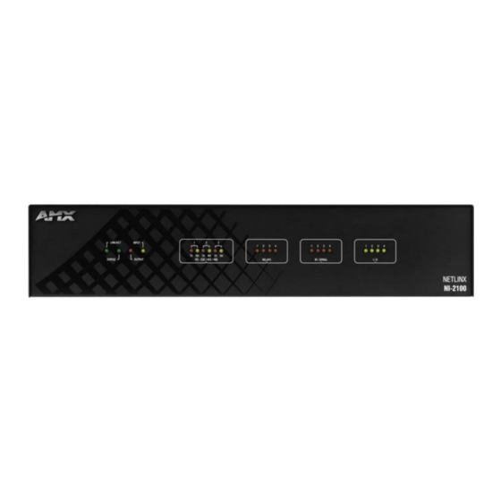
Introduction NOTE: Verify you are using the latest NI f irmware for the on-board Master. Verify you are using the latest version of NetLinx Studio (available for download from www.amx.com). NI-2100 Specif ications NI-2100 Specif ications Models Available: • NI-2100 64MB Controller (FG2105-04) The NI-2100 can be upgraded to provide one ICSHub and two ICSNet ports by installing the optional ICSNet daughter card (FG2105-10 - see Other AMX Equipment) •... - Page 8 Introduction NI-2100 Specif ications (Cont.) Ethernet Port: RJ-45 connector provides TCP/IP communication. This is an Auto MDI/MDI-X enabled port, which you can use with either straight-through or crossover Ethernet cables. The Ethernet Port LEDs show communication activity, connection status, speeds, and mode information: •...
-
Page 9: Ni-3100 Specifications
Introduction NI-3100 The NI-3100 (FG2105-05), part of the NI Series of Master Controllers, satisfies the control and automation features common in a larger area or multiple rooms, which may include integrating a larger number of devices including VCR and DVD players, projectors, lighting, thermostats, and other electronic equipment. - Page 10 Introduction NI-3100 Specif ications (Cont.) Front Panel LEDs: LINK/ACT (green): Blinks when the Ethernet cables are connected and terminated correctly. Also blinks when receiving Ethernet data packets. Status (green): Blinks to indicate that the system is programmed and communicating properly. Output (red): Blinks when the Controller transmits data, sets channels On and Off, sends data strings, etc.
- Page 11 Introduction NI-3100 Specif ications (Cont.) Other AMX • 2-pin 3.5 mm mini-Phoenix male connector (41-5026) Equipment: • CC-NSER IR/Serial cables (FG10-007-10) • ICSNet daughter card (FG2105-10) • NCK, NetLinx Connector Kit (FG2902) • STS, Serial To Screw Terminal (FG959) • Upgrade Compact Flash (factory programmed with firmware): NXA-CF2NI4G, 4 GB Flash Upgrade (FG2116-07) NI-4100 The NI-4100 (FG2105-06) provides versatility with the ability to integrate the largest number of devices in the NI Series of Master Controllers, including projectors, lighting, VCR and DVD players, thermostats, and other electronic equipment.
-
Page 12: Ni-4100 Specifications
Introduction NI-4100 Specif ications NI-4100 Specif ications Models Available: • NI-4100 64MB Controller (FG2105-06) • NI-4100/256 256MB Controller (FG2105-26) Dimensions (HWD): • 5 3/16" x 17" x 9 5/16" (13.2 cm x 43.2 cm x 23.7 cm) • RU: 3 Power Requirement: •... -
Page 13: Related Documents
Introduction NI-4100 Specif ications (Cont.) Ethernet Port: RJ-45 connector provides TCP/IP communication. This is an Auto MDI/MDI-X enabled port, which allows you to use either straight-through or crossover Ethernet cables. The Ethernet Port LEDs show communication activity, connection status, speeds, and mode information: •... -
Page 14: Installation And Upgrading
Installation and Upgrading Installation and Upgrading Installing NetLinx Control Cards (NI-4100 Only) You can install NetLinx Cards into the front card slots on the NI-4100. The cards mount horizontally through the card slot openings on the front of the enclosure. Discharge the static electricity from your body by touching a grounded object. -
Page 15: Removing Netlinx Control Cards (Ni-4100 Only)
Installation and Upgrading The D:P:S notation is used to explicitly represent a device number, port, and system. For example, 128:1:0 represents the first port on device 128 on this system. If a device is declared in a NetLinx program with just the Device number (System and Port are omitted), the NetLinx Compiler assumes it has a Port number of 1 and a System number of 0. -
Page 16: Installation Of Compact Flash Upgrades
Installation and Upgrading Chassis housing screws (top) Mounting - 6 on top Brackets - sides vary per model Compact Flash Compact Flash insert location Chassis housing screws (side) - 4 on each side of the NI-4100 - 3 on each side of the NI-3100/2100 NXC Card Slot faceplate... -
Page 17: Closing And Securing The Outer Housing
Installation and Upgrading Card Removal Grooves Insert with arrow facing towards the connector pins Removing the Compact Flash card FIG. 6 To complete the upgrade process, close and re-secure the Integrated Controller enclosure using the procedures outlined in the next section. NOTE: Any new internal card upgrade is detected by the Controller only after power is cycled. - Page 18 Installation and Upgrading Install screws Rack Mounting Holes Bracket Rack Mounting Holes Install screws Mounting Integrated Controller into an equipment rack FIG. 7 Thread the cables through the opening in the equipment rack. Allow for enough slack in the cables to accommodate for movement during the installation process.
-
Page 19: Connections And Wiring
Connections and Wiring Connections and Wiring Setting the Conf iguration DIP Switch (for the Program Port) Prior to installing the Controller, use the Configuration DIP switch to set the baud rate used by the Program port for communication. The Configuration DIP switch is located on the front of the Integrated Controllers. Baud Rate Settings Before programming the on-board Master, make sure the baud rate you set matches the communication parameters set on both your PC’s COM port and those set through your NetLinx Studio. -
Page 20: Program Port Connections And Wiring
Connections and Wiring Program Port Connections and Wiring The Integrated Controllers are equipped with a Program port located on the front of the unit. Use an RS-232 programming cable to establish a connection between this Program port to your PC's COM port. The connection provides communication with the NetLinx Integrated Controller. -
Page 21: Port Assignments And Functionality
Connections and Wiring Port Assignments and Functionality The Port Assignments are as follows: NI-2100 Port Assignments NI-3100/4100 Port Assignments Port ICSP Port # Port ICSP Port # Serial Port #1 Serial Port #1 Serial Port #2 Serial Port #2 Serial Port #3 Serial Port #3 Relays Ports (1-4) Serial Port #4... -
Page 22: Wiring Length Guidelines
Connections and Wiring Wiring Length Guidelines Refer to the following tables for the wiring length information used with the different types of NetLinx Integrated Controllers: Wiring Guidelines - NI-2100 (@ 700 mA) Wire size Maximum wiring length 18 AWG 154.83 feet (47.19 meters) 20 AWG 98.30 feet (29.96 meters) 22 AWG... -
Page 23: Using The 4-Pin Mini-Phoenix Connector For Data With External Power
Connections and Wiring Using the 4-pin Mini-Phoenix Connector for Data with External Power When using the 4-pin 3.5 mm mini-Phoenix (female) captive-wire connector for data communication and power transfer, the incoming PWR and GND cable from the 12 VDC-compliant power supply must be connected to the AxLink cable connector going to the Integrated Controller. -
Page 24: Icsnet Port: Connections And Wiring
Connections and Wiring ICSNet Port: Connections and Wiring The NI Controller must be equipped with the available ICSNet connectors for this functionality to be active. The following tables show the signal and pinouts/pairing information: ICSNet RJ-45 Signals Signal-Master Signal-Device TX + RX + TX - RX -... -
Page 25: Relay Port: Connections And Wiring
Connections and Wiring Relay Port: Connections and Wiring You can connect up to 8 independent external relay devices on both the NI-3100 and NI-4100 units (4 on the NI-2100) to the Relay connectors on the Integrated Controller. Connectors labeled A are for common; B are for output. ... -
Page 26: Ir/Serial Port: Connections And Wiring
Connections and Wiring IR/Serial Port: Connections and Wiring You can connect up to eight IR- or Serial-controllable devices to the IR/Serial connectors on the rear of the NI-4100 and NI-3100, up to four on the NI-2100 (FIG. 15). These connectors accept an IR Emitter (CC-NIRC) that mounts onto the device's IR window, or a mini-plug (CC-NSER) that connects to the device's control jack. -
Page 27: Lan (Ethernet/Rj-45 Port): Connections And Wiring
Connections and Wiring LAN (Ethernet/RJ-45 Port): Connections and Wiring NOTE: NI-x100 Controllers feature an Auto MDI/MDI-X LAN port. This provides the option of using either a standard (straight through), or a crossover LAN cable to communicate with a PC - both cable types will work. The following table lists the pinouts, signals, and pairing for the LAN connector. - Page 28 Connections and Wiring LAN Port Descriptions (Cont.) Port type Description Standard Port # ICSP Peer-to-peer protocol used for both Master-to-Master and Master-to-device communications. 1319 (UDP/TCP) For maximum flexibility, the Master can be configured to utilize a different port than 1319, or disable ICSP over LAN completely from either Telnet or the Program Port located on the rear of the Master itself.
- Page 29 © 2016 Harman. All rights reserved. NetLinx, AMX, AV FOR AN IT WORLD, HARMAN, and their respective logos are registered trademarks of HARMAN. Last Revised: Oracle, Java and any other company or brand name referenced may be trademarks/registered trademarks of their respective companies.
Need help?
Do you have a question about the AMX NI-2100 and is the answer not in the manual?
Questions and answers