Table of Contents
Advertisement
Quick Links
Advertisement
Chapters
Table of Contents

Related Manuals for Yamaha VL70-m


Summary of Contents for Yamaha VL70-m
- Page 2 Compliance with FCC regulations does not guaran- This applies only to products distributed by YAMAHA CORPORATION OF AMERICA. NEDERLAND / NETHERLAND • Dit apparaat bevat een lithium batterij voor geheugen back-up.
-
Page 3: Special Message Section
This product should be used only with the components supplied or; a cart, rack, or stand that is recommended by Yamaha. If a cart, etc., is used, please observe all safety markings and instructions that accompany the accessory product. - Page 4 Thank you for choosing a Yamaha VL70-m Virtual Acoustic Tone Generator. The VL70-m is a monophonic tone generator incor- porating Yamaha’s revolutionary “Virtual Acoustic Synthesis” tone generation system — based on the most advanced computer physical modeling technology. Virtual Acoustic Synthesis produces sound that is more realistic, more expressive, and more musical than any other system available at this time.
-
Page 5: About The Manual
The following conventions are used through the VL70-m manuals to avoid confusion and make the text easier to read. Buttons & Controls Button and control names used on the VL70-m panel appear in the text in capital letters within square brackets: “the [ENTER] button”, for example. Parameter Ranges An ellipsis is used to indicate a range of parameter values: e.g. -
Page 6: Table Of Contents
VA Advantages ..... . . 6 The VL70-m Model ....7 The Instrument . - Page 7 Filter & Envelope Generator Editing Amplitude & Filter EG ..66 Pitch & Embouchre EG ..66 Accessing & Editing the Filter & EG Parameters .
-
Page 8: Precautions
OFF prior to connecting or disconnecting audio and MIDI cables. MIDI Connections • When connecting the VL70-m to MIDI equipment, be sure to use high- quality cables made especially for MIDI data transmission. • Avoid MIDI cables longer than about 15 meters. Longer cables can pick up electrical noise that can causes data errors. - Page 9 Data Backup • The VL70-m contains a special long-life battery that retains the contents of its internal memory even when the power is turned OFF. The backup battery should last for several years. When the backup battery needs to be replaced “Battery Low!”...
-
Page 10: Virtual Acoustic Synthesis
… well, musical! Yamaha Virtual Acoustic Synthesis is simply the most musical tone generation system ever created. • The VL70-m sounds better, has more depth, and is more realistic in the musical sense than any other tone generation system. -
Page 11: The Vl70-M Model
The VL70-m Model The overall VL70-m model or “algorithm” consists of three main blocks: the instrument, controllers, and modifiers. In schematic form these blocks are arranged as follows: Controllers (also envelopes) Instrument Modifiers Sound out Virtual Acoustic Synthesis... -
Page 12: The Instrument
One of the remarkable features of the VL70-m’s Virtual Acoustic Synthesis system is that just about any driver can be used with any type of pipe or string. Virtual Acoustic Synthesis The Instrument... -
Page 13: The Controllers
In a string instrument it comes from the player’s arm movement, transmitted to the string via a bow. These elements actually form an important part of the sound generating system and, in the VL70-m model, are included in the controllers block. The player also influences the sound of the instrument by playing the keys, tone holes, or frets, and this aspect of control constitutes another part of the controllers block. -
Page 14: The Modifiers
Although only simplified treble and bass parameters are available via the VL70-m controls, the full range of equalizer parameters can be accessed via the Yamaha VL70-m Expert Editor software (page 25). -
Page 15: There's More
And, of course, there’s a comprehensive selection of utility functions that give the VL70-m maximum versatility and convenience. Now that you understand the basics, dive in and find out what the VL70-m can really do. Virtual Acoustic Synthesis... -
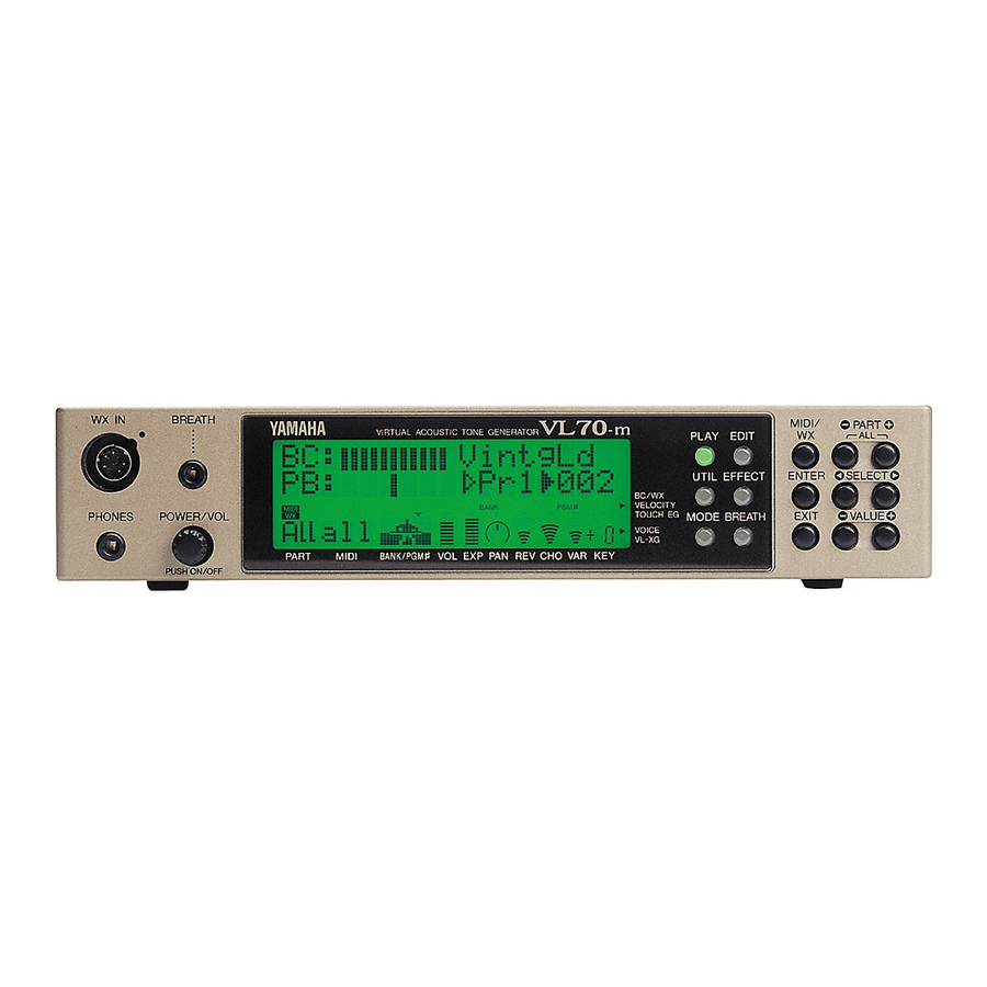
Page 16: The Controls & Connectors
The Controls & Connectors The following brief descriptions of the VL70-m controls and connectors should help you to understand the overall logic of the interface. [POWER/VOL] Control Press to turn power ON or OFF. Rotate to adjust overall output volume (clockwise to increase the volume). - Page 17 This button is used to exit from sub-modes and cancel certain operations. No matter where you are in the VL70-m display structure, pressing the [EXIT] button (a number of times if necessary) will eventually return you to the PLAY mode.
-
Page 18: Rear Panel
15 OUTPUT L/MONO and R Jacks These are the main stereo outputs from the VL70-m. Be sure to connect both outputs to the appropriate channels of a stereo sound system in order to appreciate the full quality of the VL70- m sound and effects. -
Page 19: Setting Up
Yamaha dealer to power the VL70-m. The use of an incompatible adaptor may cause irreparable damage to the VL70-m, and might pose a serious shock hazard! • Be sure to unplug the AC adaptor from the AC mains socket when the VL70-m is not in use. DC-IN... -
Page 20: Midi Connections
• For detailed MIDI specifications refer to the “MIDI Data Format” on page 26 of the List Book. • When using the VL70-m with other MIDI equipment, it is a good idea to refer to the MIDI specifications (implementation chart, MIDI data format) of the equipment used to ensure compatibility. -
Page 21: Breath Controller
Breath Controller If you will be using the VL70-m with a keyboard, a breath controller is an essential expressive tool — both for realistic expression with wind-instru- ment voices and unprecedented expressive control with string voices. Plug an optional Yamaha BC3, BC2 or BC1 Breath Controller into the front-panel breath controller jack. -
Page 22: Wx-Series Wind Midi Controller
WX-series Wind MIDI Controller: NOTES • If a WX controller is unplugged while the VL70-m power is on, the breath level may remain fixed at “0” and subsequently played notes may not sound. If this happens, turn the VL70-m power off and then on again. -
Page 23: G50 Guitar Midi Converter
MIDI control to guitar players for the first time. Naturally, the VL70-m is an ideal tone generator for use with a MIDI guitar system based on the G50. -
Page 24: Connecting To A Personal Computer
MIDI interface. IMPORTANT! • If the VL70-m is to be connected to a computer via the TO HOST connector and a MIDI controller via the MIDI IN connector, the “echo back” function of the music software or sequencer you are using must be turned “on”... -
Page 25: Connecting To An Ibm Pc/At Series Computer
Connecting to an IBM PC/AT Series Computer Connect the TO HOST connector of the VL70-m to the RS-232C port on your IBM computer, using a standard 8-pin MINI DIN Set the TO HOST selector to the “PC-2” position. Refer to your software owner’s manual for information on any settings you might have to make on the computer side. -
Page 26: Audio Connections
The left and right channel signals are automatically combined and delivered via the L/ MONO jack when a single phone plug is inserted in this jack and the R output jack is left unconnected. • Make sure that both the VL70-m and your sound system are turned OFF when making connections. Setting Up... -
Page 27: Power-On Procedure
ON or OFF. The VL70-m is programmed to receive this data and respond accordingly, so it is prefer- able to turn the VL70-m ON before turning the controlling device ON. -
Page 28: Play The Demo
• When the demo is played all system setup parameters and current voice are initialized. If your VL70-m memory contains data you want to keep, be sure to use the bulk dump function (page 100) to save the data to an external MIDI data recorder or other appro- priate storage device before playing the demo. -
Page 29: The Supplied Demo Disk
SMF (Standard MIDI File — format 0) song files. All of the demo songs use the VL70-m for the main melody line, while a second XG tone generator (Yamaha MU50 or MU80 for example) supplies the backing. -
Page 30: Voice Organization And Sound Module Modes
PRESET 1, PRESET 2, or CUSTOM bank. Edited voices can only be stored to the INTERNAL bank, and only when the VL70-m is set to the VOICE sound module mode (page 29). -
Page 31: The Vl70-M Sound Module Modes
In this mode the VL70-m functions as a “standard” tone generator module. The VOICE mode should be used when the VL70-m is being used alone or with other non-XG tone generators/synthesizers (see “VL Extension for XG”, page 30). -
Page 32: The Vl-Xg Mode
In this mode the VL70-m functions as an “XG expansion” tone generator module. The VL-XG mode should be selected when the VL70-m is being used with other XG tone generators/synthesizers to play music data created for tone generators complying with the Yamaha XG format (see “VL Extension for XG”, page 30). -
Page 33: Selecting The Voice Or Vl-Xg Sound Module Mode
PLAY mode. The VOICE or VL-XG sound module mode is selected as follows: 1. Press the [MODE] Button Press the [MODE] button access the VL70-m sound module modes selection function. 2. Select the VOICE or VL-XG Mode Use the VALUE [-] and [+] buttons to select the “VOICE”... -
Page 34: Vl Extension For Xg
And since XG is totally upward compatible with GM, GM data can be accurately reproduced on any XG tone generator. * The VL70-m does not contain the basic set for the XG format. Voice Organization and Sound Module Modes The VL Extension for XG (“VL Extension for XG”... -
Page 35: The Voice Play Mode
The VOICE PLAY Main Control Mode This mode is initially selected when the VL70-m power is turned on. If the sub-control mode is active (see page 34), the main control mode can be selected by simultaneously pressing the PART [-] and [+] buttons. - Page 36 (see “Voice Organization” on page 26). (Program Number) Settings: 001 … 128 Selects the voice to played on the VL70-m. The PRESET 1 and PRESET 2 banks each have voice numbers from “001” to “128”, while the INTER- NAL bank has voice numbers from “001” to “064”, and the CUSTOM bank has voice numbers...
- Page 37 ChoRtn (Chorus Return) Settings: 000 … 127 Adjusts the level of the signal returned from the VL70-m chorus effect stage. The higher the value, the higher the level of the chorus signal. VarRtn (Variation Return) Settings: 000 … 127 Adjusts the level of the signal returned from the VL70-m variation effect stage.
-
Page 38: The Voice Play Sub-Control Mode
The VOICE PLAY Sub-control Mode The sub control mode can be selected from the main control mode by simultaneously pressing the PART [-] and [+] buttons. The VOICE PLAY sub-control mode display looks like this: • Receive Channel • Bank Pointer •... - Page 39 “001” to “006”. RevSend (Reverb Send) Settings: 000 … 127 Adjusts the level of the signal sent to the VL70-m reverb effect stage. The higher the value, the higher the level of the reverb send signal. ChoSend (Chorus Send) Settings: 000 …...
-
Page 40: The Vl-Xg Play Mode
When the VL-XG sound module mode is selected (see “The VL70-m Sound Module Modes, page 27), pressing the [PLAY] button engages the VL70-m VL- XG PLAY mode. In this mode the VL70-m can be used as an “XG expansion” tone generator module with other XG tone generators/synthesizers to play music data created for tone generators complying with the Yamaha XG format (see “VL Extension for XG”, page 30). -
Page 41: The Vl-Xg Play Main Control Mode
The VL-XG PLAY Main Control Mode This mode is initially engaged when the VL-XG sound module mode is selected. If the sub-control mode is active (see page 40), the main control mode can be selected by simultaneously pressing the PART [-] and [+] buttons. The VL-XG PLAY main control mode display looks like this: PART MIDI... - Page 42 112 through 119 allow selection of voice numbers from “022” to “128”, although some voice num- bers are skipped since the VL70-m does not have a full basic XG voice set. The PRESET 1 and PRESET 2 banks each have voice numbers from “001”...
- Page 43 RevSend (Reverb Send) Settings: 000 … 127 Adjusts the level of the signal sent to the VL70-m reverb effect stage. The higher the value, the higher the level of the reverb send signal. ChoSend (Chorus Send) Settings: 000 … 127 Adjusts the level of the signal sent to the VL70-m chorus effect stage.
-
Page 44: The Vl-Xg Play Sub-Control Mode
The VL-XG PLAY Sub-control Mode The sub control mode can be selected from the main control mode by simultaneously pressing the PART [-] and [+] buttons. The VL-XG PLAY sub-control mode display looks like this: • Device Number • Master Volume The various parameters in this mode are selected via the SELECT [<] and [>] buttons. - Page 45 Settings: 001 … 016, all The Device Number parameter must be set prop- erly when you want to transmit or receive MIDI system exclusive data to or from another VL70-m or other MIDI device (system exclusive data includes voice parameters, system setup param- eters, etc).
-
Page 46: Controllers & Control Editing
— assigned to the required controller parameter. The effectiveness of the VL70-m as a musical instrument depends to a great deal on how well you learn to use these controllers. Since the VL70-m sound is produced by a computer-based physical model rather than a oscillator-based tone generator, there are no hard-and-fast rules as to how any controller will actually affect the sound. -
Page 47: Physical Controllers
Like the modulation wheel, a foot controller connected to your Foot Controller (MIDI control keyboard or other MIDI device can be assigned to any VL70-m controller parameter. change no. 04) Keyboard aftertouch allows you to control any controller Aftertouch parameter by the pressure you apply to a key after it is initially pressed. - Page 48 Controllers & Control Editing Control No. Controller off(32) off (used by Bank Select LSB) 33~37 Unassigned Data Entry LSB 39~63 Unassigned Hold1 Portamento Switch Unassigned Soft Pedal 68~70 Unassigned Harmonic Content Release Time Attack Time Brightness 75~90 Unassigned Effect Send Level (Reverb Effect) Unassigned Effect Send Level 3 (Chorus...
-
Page 49: Vl70-M Controller Parameters
VL70-m Expert Editor software (page 25). The Harmonic Enhancer can vary the harmonic structure of the Harmonic sound over a wide range. Since most VL70-m voices have Enhancer sufficient natural harmonic content, the Harmonic Enhancer is actually only used on a few voices. Therefore changing the controller destination with many voices will produce either no change in the sound or a simple change in amplitude. -
Page 50: Accessing & Editing The Control Parameters
Accessing & Editing the Control Param- eters The CONTROL EDIT mode can be accessed from the VOICE PLAY mode as follows: 1. Press [EDIT] Press the [EDIT] button to go to the VOICE EDIT sub-mode menu. 2. Select the CONTROL Sub-mode Use the SELECT [<] and [>] buttons to select the CONTROL sub-mode, if necessary. - Page 51 6. Repeat As Necessary Repeat steps 4 and 5 to edit as many parameters as required. 7. Exit When Done Press ther [EXIT] button to return to the VOICE EDIT sub-mode menu, or the [PLAY] button to return to the VOICE PLAY mode when you’re finished editing.
-
Page 52: The Control Edit Parameters
The Control Edit Parameters Please note that a number of CONTROL EDIT parameters which are avail- able in the VOICE sound module mode are not available in the VL-XG sound module mode (page 28). The parameter numbers are therefore different in each mode. - Page 53 Embouchure ... 57 22: Emb CC No. (Embouchure Control Change Number) 23: EmbUpprDpt (Embouchure Upper Control Depth) 24: EmbLowrDpt (Embouchure Lower Control Depth) 25: Emb Mode (Embouchure Mode) Tonguing ... 58 26: Tng CC No. (Tonguing Control Change Number) 27: TngCtrlDpt (Tonguing Control Depth) 28: Tng Curve (Tonguing Curve)
-
Page 54: Vl-Xg Sound Module Mode Control Edit Parameters
VL-XG Sound Module Mode Control Edit Parameters Refer to the page numbers listed for full details on each parameter. Pitch Bend ... 52 Modulation Wheel ... 53 Aftertouch ... 53 Assignable Controller ... 54 Pressure ... 55 Embouchure ... 57 Tonguing ... - Page 55 Throat Formant ... 62 24: Thr CC No. (Throat Formant Control Change Number) 25: ThrCtrlDpt (Throat Formant Control Depth) Harmonic Enhancer ... 62 26: Hrm CC No. (Harmonic Enhancer Control Change Number) 27: HrmCtrlDpt (Harmonic Enhancer Control Depth) Damping ... 63 28: Dmp CC No.
-
Page 56: Control Edit Parameter Descriptions
The same applies to Virtual Acoustic Synthesis: in the VL70-m pitch bend is simulated by manipulating the appropriate pipe/string length and driver characteristics. As a result, the pitch bend range may not always be “mathemati-... -
Page 57: Modulation Wheel
Modulation Wheel : MWLFO PMod (04) • Modulation Wheel LFO Pitch Modulation • Settings: 000 … 127 Sets the amount of LFO pitch modulation applied by the modulation controller (e.g. the modulation wheel on a keyboard — MIDI control change number 01). -
Page 58: Assignable Controller
11) will function as volume control or as breath controller. When set to “Vol” expression will affect volume, but when set to “BC” expression will produce the same effect as a breath controller connected to the VL70-m BREATH jack, affecting the same breath-controlled parameters. -
Page 59: Pressure
Pressure : Prs CC No. (12) • Pressure Control Change Number • Settings: off… 95, AT, VEL, PB “Pressure” corresponds to the amount of breath pressure applied to a reed or mouthpiece, or the speed of the bow applied to a string. Pressure variations affect both volume and timbre. -
Page 60: Amplitude
Some voices use very little filter processing at all. Changing the filter settings may not produce a particularly notice- able effect. For detailed filter parameter pro- gramming use the VL70-m Expert Editor software (page 25). 17: FilCtrlDpt (VOICE mode only) •... -
Page 61: Embouchure
pressure or higher modulation wheel position), while minus values cause a decrease in amplitude in response to higher controller values. The “Depth” setting is reflected in the graph at the bottom of the display — the horizontal axis represents the controller value and the vertical axis represents amplitude. -
Page 62: Tonguing
24: EmbLowrDpt (VOICE mode only) • Embouchure Lower Control Depth • Settings: -127 … +127 Sets the amount of variation produced by the controller assigned to embouchure when the controller is set to it minimum position (e.g. a modulation wheel rolled all the way down). The higher the value the greater the variation. -
Page 63: Scream
: TngCtrlDpt (17) • Tonguing Control Depth • Settings: -127 … +127 (VL-XG Mode: -64 … +63) Sets the amount of variation produced by the controller assigned to tonguing. The higher the value the greater the variation. Positive values cause an decrease in tonguing in response to higher controller values (e.g. -
Page 64: Breath Noise
31: Scr Curve (VOICE mode only) • Scream Curve • Settings: -16 … +16 Determines the relationship between the controller value and scream. When set to “+00” the relation- ship is linear. That is, a change in the controller value produces a corresponding change in scream effect. -
Page 65: Growl
represents the controller value and the vertical axis represents breath noise. • The amount of breath noise produced also depends on pressure, so the breath noise curve indicated by the graph at the bottom of the display may not always accurately reflect the perceived curve. -
Page 66: Throat Formant
Throat Formant : Thr CC No. (24) • Throat Formant Control Change Number • Settings: off… 95, AT, VEL, PB “Throat Formant” controls the characteristics of the simulated player’s lungs, trachea, and oral cavity. Can add a realistic “roughness” to the sound. -
Page 67: Damping
Therefore changing the controller destination with many voices will produce either no change in the sound or a simple change in amplitude. For detailed harmonic enhancer programming use the VL70-m Expert Editor software (page 25). : HrmCtrlDpt (27) • Harmonic Enhancer Control Depth •... -
Page 68: Absorption
Sets the amount of variation produced by the controller assigned to damping. The higher the value the greater the variation. Positive values cause a decrease in damping in response to higher controller values (e.g. increased breath pressure or higher modulation wheel position), while minus values cause an increase in damping in response to higher controller values. - Page 69 49: Abs Curve (VOICE mode only) • Absorption Curve • Settings: -16 … +16 Determines the relationship between the controller value and absoprtion. When set to “+00” the relationship is linear. That is, a change in the controller value produces a corresponding change in absorption.
-
Page 70: Filter & Envelope Generator Editing
Amplitude & Filter EG The Amplitude & Filter Envelope Generator controls both the amplitude of the sound and the cutoff frequency of the VL70-m filter from note attack to release. This envelope generator has three parameters which can be edited via the VL70- m panel: attack time, decay time, and release time. -
Page 71: Accessing & Editing The Filter & Eg Parameters
Accessing & Editing the Filter & EG Param- eters The FILTER & EG EDIT mode can be accessed from the PLAY mode as follows: 1. Press [EDIT] Press the [EDIT] button to go to the EDIT sub-mode menu. 2. Select the FIL&EG Sub-mode Use the SELECT [<] and [>] buttons to select the FIL&EG sub-mode, if necessary. - Page 72 5. Edit the Selected Parameter Use the VALUE [-] and [+] buttons to set the value of the selected parameter as required. 6. Repeat As Necessary Repeat steps 4 and 5 to edit as many parameters as required. 7. Exit When Done Press the [EXIT] button to return to the EDIT sub-mode menu, or the [PLAY] button to return to the PLAY mode when you’re finished editing.
-
Page 73: The Filter & Eg Edit Parameters
The Filter & EG Edit Parameters Please note that a number of FIL&EG EDIT parameters which are available in the VOICE sound module mode are not available in the VL-XG sound module mode (page 28). The parameter numbers are therefore different in each mode. -
Page 74: Vl-Xg Sound Module Mode Filter & Eg Edit Parameters
VL-XG Sound Module Mode Filter & EG Edit Parameters Refer to the page numbers listed for full details on each parameter. Filter Amplitude & Filter Envelope ... 72 Pitch & Embouchure Envelope ... 73 Filter & Envelope Generator Editing ... 71 01: CutoffFreq (Cutoff Frequency) 02: Resonance... -
Page 75: Filter & Eg Edit Parameter Descriptions
Cutoff frequency : CutoffFreq (01) • Cutoff Frequency • Settings: -64 … +63 Sets the cutoff frequency of the VL70-m filter. : Resonance (02) • Resonance • Settings: -64 … +63 This parameter produces a resonant peak at the filter’s cutoff frequency, thereby emphasizing frequency components at that frequency. -
Page 76: Amplitude & Filter Envelope
the breakpoint note specified by the “CutoffScBP” parameter, above. A setting of “+00” produces no key scaling. Positive values apply scaling to notes below the breakpoint (i.e. on a keyboard, notes to the left of the breakpoint), producing a gradual lowering of the cutoff frequency down the scale. -
Page 77: Pitch & Embouchure Envelope
: ReleaseTime (08) • Amplitude & Filter Envelope Release Time • Settings: -64 … +63 Sets the release time of the amplitude & filter envelope generator. “Release time” refers to the length of time it takes for the envelope to fall to “zero”... - Page 78 : PEGAtakTime (10) • Pitch & Embouchure Envelope Attack Time • Settings: -64 … +63 Sets the attack time of the pitch & embouchure envelope generator. In this case “attack time” refers to the length of time it takes for the pitch envelope to reach normal pitch (“+00”...
-
Page 79: Other Edit Parameters
Other Edit Parameters The OTHERS EDIT mode provides access to a range of editable voice param- eters that do fall into the CONTROLLER or FILTER & EG categories. Accessing & Editing the “Others” Param- eters The OTHERS EDIT mode can be accessed from the PLAY mode as follows: 1. - Page 80 5. Edit the Selected Parameter Use the VALUE [-] and [+] buttons to set the value of the selected parameter as required. 6. Repeat As Necessary Repeat steps 4 and 5 to edit as many parameters as required. 7. Exit When Done Press ther [EXIT] button to return to the EDIT sub-mode menu, or the [PLAY] button to return to the PLAY mode when you’re finished editing.
-
Page 81: The "Others" Edit Parameters
The “Others” Edit Parameters Please note that a number of OTHERS EDIT parameters which are available in the VOICE sound module mode are not available in the VL-XG sound module mode (page 28). The parameter numbers are therefore different in each mode. -
Page 82: Vl-Xg Sound Module Mode "Others" Edit Parameters
VL-XG Sound Module Mode “Others” Edit Parameters Refer to the page numbers listed for full details on each parameter. Vibrato ... 79 Detune ... 79 Assignment ... 80 Velocity Sensitivity ... 81 Note Limits ... 81 Portamento ... 82 Dry Level ... 82 Other Edit Parameters 01: Vib Rate (Vibrato Rate) -
Page 83: Others" Edit Parameter Descriptions
• Detune • Settings: -12.8 … +12.7 Hz The “Detune” parameter allows the pitch of the VL70-m to be shifted slighlty upward or down- ward to produce detune effects in relation to other VL70-m units or other tone generators being used with the VL70-m. -
Page 84: Assignment & Expansion
(polyphony). The number preceding the “>” should be set to correspond to the number of VL70-m units to be used. The number following the “>” should be set to a different consecutive number for each VL70-m unit. -
Page 85: Velocity Sensitivity
(06) • Velocity Sensitivity Depth • Settings: 000 … 127 Determines how the VL70-m responds to keyboard velocity. When set to “000”, keyboard velocity (i.e. how fast or hard the keyboard is played) has no effect on the sound. At values higher than “001”,... -
Page 86: Portamento
(12) • Dry Output Level • Settings: 000 … 127 Sets the output level of the VL70-m “dry” (i.e. without effects) sound. The higher the value the higher the dry output level. Increased dry levels produce a relative reduction in the perceived “depth”... - Page 87 17: Voice Name (VOICE mode only) • Voice Name • Settings: A voice name of up to 8 characters. To enter a voice name first select the “Voice Name” parameter and press the [ENTER] button. The current voice name will appear between square brackets on the display with the first character flashing (the flashing character is selected for editing).
-
Page 88: The Store Function
The Store Function Once you’ve created a new voice in the edit mode, it’s necessary to store the voice to one of the VL70-m INTERNAL memory locations otherwise the edited data will be lost when a new voice is selected. - Page 89 Press the [ENTER] button to store the voice. “Executing” will appear on the display briefly while the data is being stored, then the VL70-m will return to the EDIT sub-mode menu. Press [EXIT] rather than [ENTER] if you want to abort the store operation.
-
Page 90: Effects & Effect Editing
Effects & Effect Editing The VL70-m features a versatile internal effects system which consists of four independent effect stages: REVERB, CHORUS, VARIATION, and DISTOR- TION. Of these the REVERB and CHORUS stages function as “system ef- fects”, the VARIATION stage can be used either as a system or “insertion”... -
Page 91: When The Variation Stage Is A System Effect
parameters available in the PLAY mode (pages 32 and 41). The “SendCho Rev” parameter (page 91) can be used to send some or all of the output from the chorus stage to the reverb stage. If the the “SendCho Rev” parameter is set to maximum and the “ChoRtn”... -
Page 92: Accessing & Editing The Effect Parameters
Accessing & Editing the Effect Parameters The EFFECT sub-modes — REV, CHO, VAR, and DIST — and the param- eters they contain can be accessed from the PLAY mode as follows: 1. Press [EFFECT] Press the [EFFECT] button to go to the EFFECT sub-mode menu. 2. - Page 93 6. Repeat As Necessary Repeat steps 4 and 5 to edit as many parameters as required. 7. Exit When Done Press ther [EXIT] button to return to the EFFECT sub-mode menu, or the [PLAY] button to return to the PLAY mode when you’re finished editing. IMPORTANT! •...
-
Page 94: The Reverb Parameters
The Reverb Parameters The reverb effects are essential to give your sound ambience and a sense of dimension, adding warmth and depth to an otherwise dry sound. Type • Reverb Type • Settings: NO EFFECT, HALL 1, HALL 2, ROOM 1, ROOM 2, ROOM 3, STAGE 1, STAGE 2, PLATE, WHITE ROOM, TUNNEL, CANYON, BASEMENT Selects the reverb type, or “NO EFFECT”... -
Page 95: The Chorus Parameters
The Chorus Parameters The VL70-m chorus stage actually includes a number of modulation-type effects that can be used to give your sound extra animation and life. Type • Chorus Type • Settings: NO EFFECT, CHORUS 1, CHORUS 2, CHORUS 3, CELESTE 1, CELESTE 2, CELESTE 3, FLANGER 1, FLANGER 2, SYMPHONIC, PHASER Selects the chorus type, or “NO EFFECT”... -
Page 96: The Variation Parameters
The Variation Parameters The variation stage includes reverb, delay, echo, modulation, distortion, wah, and a range of other effects. Type • Variation Type • Settings: NO EFFECT, HALL 1, HALL 2, ROOM 1, ROOM 2, ROOM 3, STAGE 1, STAGE 2, PLATE, DELAY LCR, DELAY L,R, ECHO, CROSSDELAY, ER1, ER2, GATE REV, REVRS GATE, KARAOKE 1, KARAOKE 2, KARAOKE 3, CHORUS 1, CHORUS 2, CHORUS 3,... - Page 97 control allows one of the selected variation effect parameters to be controlled in real time via assign- able controller 1 (page 54). The parameter which can be controlled is individually preset for each variation effect type (see the separate “List Book”). The “AC1VarCtrl”...
-
Page 98: The Distortion Parameters
The Distortion Parameters Distortion is an excellent way to drastically change a sound — although subtle distortion settings can produce surprisingly delicate variations. Type • Distortion Type • Settings: THRU, DISTORTION, OVERDRIVE, 3-BAND EQ Selects the distortion type, or “THRU” if no distortion effect is required. -
Page 99: Breath Settings
Breath Settings The Breath Setting includes a number of setting that determine how the VL70- m responds to breath control from a breath controller, a Yamaha WX-series Wind MIDI controller, or MIDI. Accessing & Editing the Breath Parameters The BREATH parameters can be accessed and edited from the PLAY mode as follows: 1. -
Page 100: The Breath Parameters
Specifies the MIDI control change number to be used for breath control when breath control is applied from a breath controller, WX-series Wind MIDI Controller, or via the VL70-m MIDI IN connector. When “BC” is selected control change number “02” (breath control) is used for breath copntrol. -
Page 101: The Utility Mode
The Utility Mode The UTILITY mode provides access to a range of parameters that affect basic operation of the VL70-m, and some functions that contribute to system flexibil- ity. Select the UTILITY sub-mode menu from the PLAY mode by pressing the [UTILITY] button. -
Page 102: The System Parameters
M.Tune • Master Tuning • Settings: -102.4c … +102.3c Fine tunes the overall pitch of the VL70-m in 0.1- cent steps (a “cent” is 1/100th of a semitone). The maximum minus and plus settings produce a downward or upward pitch shift of just over a semitone. - Page 103 • When the VL-XG sound module mode is selected and a program change number correspond- ing to a VL70-m voice is received, the “NoteFilter” parameter is automatically set to the channel on which the program change number was received. This does not occur in the VOICE sound module mode.
-
Page 104: The Dump Out Function
The Dump Out function allows VL70-m setup and system exclusive data to be transmitted to a second VL70-m or an external MIDI storage device such as the Yamaha MDF2 MIDI Data Filer via the MID OUT or TO HOST connec- tor. - Page 105 2. Press [ENTER] Press the [ENTER] button to go to the confirmation/select display for the selected data type. 3. Select “ALL” or a Single Voice for CUSTOM or INTERNL If you have selected the CUSTOM or INTERNL data type, you can use the VALUE [-] and [+] buttons at this point to specify whether you want to transmit “ALL”...
-
Page 106: The Initialize Function
The Initialize Function The VL70-m Initialize function includes two sub-modes — “Factory Set” and “System Initialize”. “Factory Set” initialization restores all VL70-m data to the initial factory settings … including all Custom and Internal voices. “System Initialize” restores all system setup parameters (page 98) to their default settings. -
Page 107: Appendix
Press the [EXIT] button to return to the previous display. With the VL70-m it is possible to control just about any parameter via MIDI system exclusive messages from an external MIDI device. This makes it possibe, for example, to change filter or EG settings while playing, to change the sound as required. -
Page 108: The Message Window
The VL70-m Message Window function makes it possible to display text messages up to 32 characters in length on the VL70-m display in the PLAY mode. The messages can be transmitted in the form of a data string from an external MIDI device, and will appear on the VL70-m display for about 3 seconds. -
Page 109: Bitmap Window
Bitmap Window The VL70-m Bitmap Window function makes it possible to display 16 x 16 dot icons and simple animation sequences on the VL70-m display in the PLAY mode. The bitmap data can be transmitted in the form of a data string from an external MIDI device, and will appear on the VL70-m display for about 3 seconds. -
Page 110: Checksum
5. Plug the data derived from the bitmap design into the “xx xx ... xx xx” portion of the bitmap window data format, and you have the data stream required to display the design on the VL70-m display. Appendix Checksum Some VL70-m system exclusive message require a “checksum”... -
Page 111: Troubleshooting
The VL70-m is a very versatile tone generator with many features and functions that affect operation. In many cases, what appears to be a fault with the VL70-m can actually be traced to an improperly set parameter or something as simple as a bad connection. - Page 112 Is the amplifier/mixer power turned on? • Is the amplifier/mixer volume set to an appro- priate level? • Is the VL70-m volume control set to an appro- priate level? • Are the VL70-m outputs properly connected to the amplifier/mixer inputs? •...
- Page 113 • Are the parameters to be controlled by the breath controller set properly (page 48)? • If the VL70-m is connected to a computer via the TO HOST connector, is the computer “echo back” function set properly (page 20)? •...
-
Page 114: Answers To Some Common Questions
Answers to Some Com- mon Questions 1. The VL70-m is a monophonic tone generator. Why is the “poly” mode initialy selected when the VL-XG sound module mode is engaged? This is to provide compatibility between the currrent XG format and future polyphonic VL- series tone generators. - Page 115 The same applies to Virtual Acoustic Synthesis: in the VL70-m pitch bend is simulated by manipulating the appropriate pipe/string length and driver characteristics. As a result, the pitch bend range may not always be “mathemati-...
-
Page 116: Error Messages
Error Messages When an operational error or other problem occurs, the VL70-m will display one of the following error messages to inform you of the problem. Battery Low! The internal backup battery needs to be replaced. Have the battery replaced by qualified Yamaha service personnel. -
Page 117: Specifications
Specifications Tone Generator Type S/VA (Self-oscillating Virtual Acoustic Synthesis: VLR Algo- rithm) Modifiers Harmonic Enhancer Dynamic Filter Equalizer Resonator Effects Reverb: 12 types Chorus: 10 types Variation: 44 types Distortion: 3 types Polyphony 1 note (monophonic) Sound Module Modes Voice Mode VL-XG Mode (VL extension for XG) Memory... -
Page 118: Index
Index Absorption ........45 Absorption Control Change Number ... . 64 Absorption Control Depth . - Page 119 Harmonic Enhancer Control Change Number ..62 Harmonic Enhancer Control Depth ....63 Harmonic Enhancer Curve ..... 63 Harmonic enhancer .
- Page 120 VL-XG sound module mode ....28 VL70-m model ....... . 7 Voice Level .
- Page 122 For details of products, please contact your nearest Yamaha or the authorized distributor listed below. Pour plus de détails sur les produits, veuillez-vous adresser à Yamaha ou au distributeur le plus proche de vous figurant dans la liste suivante. NORTH AMERICA CANADA Yamaha Canada Music Ltd.
- Page 123 M.D.G., EMI Division © Yamaha Corporation 1996 VV11820 606POCP3.2-01A0 Printed in Japan...
Need help?
Do you have a question about the VL70-m and is the answer not in the manual?
Questions and answers