
Related Manuals for Hyco Omega


Summary of Contents for Hyco Omega
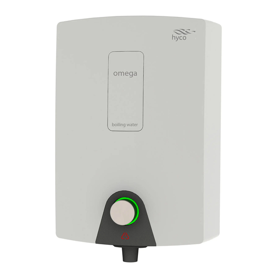
- Page 1 Product Instruction Manual Omega OMEG3, OMEG5 Wall Mounted Boiling Water Heater v23.11.3...
-
Page 2: Important Safety Points
Overview Thank you for purchasing an Omega wall mounted boiling water heater. Available in 3 and 5 litre capacities, it will provide hot water for making tea and coffee in the work place. Please read and follow these instructions to ensure that installation and operation are as simple and safe as possible. - Page 3 This appliance must be earthed. This appliance is intended to be permanently connected to the water mains and should not be connected by a detachable hose-set. Only connect this appliance to a water supply that meets the min/max pressures specified in the specifications section of this manual. Do not confuse the vent and the inlet pipes –...
-
Page 4: Installation
1. Installation 1(a) Remove the Cover Diagram 1 Diagram 2 • Lever the outlet nozzle away from the surround as shown (diagram 1). A click indicates the nozzle is successfully detached from the surround. Lower the outlet nozzle to unhook it from the surround (diagram 2). •... - Page 5 1(b) Select Mounting Position Ensure the mounting surface is suitable for the weight of the appliance when full. Parts of this appliance – especially the vent pipe and tap– can become very hot in use and can also generate steam. Consider and avoid the risk of injury to people or damage to property when installing the appliance.
-
Page 6: Plumbing Connection
1(c) Secure to Wall Ensure there are no hidden cables or pipework before commencing any drilling. • Ensuring a level, mark the two upper screw positions onto the mounting surface (diagram 5), drill and plug the holes with the provided plugs. Insert the provided screws into the plugs leaving around 3- 4 mm of the thread exposed. - Page 7 The appliance should only be used with the tap provided. Do not attempt to change or modify in any way. Do not confuse the vent and the inlet pipes – serious damage may result. The appliance will malfunction if steam cannot easily escape via the vent pipe. Failure to comply with the venting requirements detailed in these instructions may cause permanent damage to the appliance and will invalidate the warranty.
- Page 8 • For the vent connection it is important that the vent pipe installation adheres to the following specification; - Falls continuously. - Has a maximum total length of 400mm before any air gap. - Is open to the atmosphere (no blockages). - All fittings must be rated for continuous operation at a minimum of 100°C.
-
Page 9: Electrical Connection
Diagram 8 Diagram 9 4. Electrical Connection The appliance must be permanently connected to the electrical supply through an appropriately rated isolating switch with a contact separation in all poles. Only connect the appliance to an electrical supply that meets the specification detailed on the rating label. -
Page 10: Operation
5. Commissioning (first power on) • Ensure water supply is on. • Switch power on. • Automatic commissioning will then commence under the control of the electronic circuit board. The (automatic) stages in commissioning are as follows: • At first power on, the water tank will completely fill with cold water through the solenoid valve. -
Page 11: Dispensing Water
Dispensing Water • The flow of water is controlled by rotating the control knob in the centre of the status ring. Anti clockwise to increase and clockwise to decrease / stop the flow of boiling water. • The water is dispensed from the grey nozzle at the base of the appliance. 7. -
Page 12: Cleaning And Maintenance
8. Cleaning and Maintenance The appliance should only be installed and maintained by a competent person in accordance with any local electrical and plumbing regulations. Cleaning and user maintenance shall not be made by children without supervision. Do not use abrasive or corrosive chemicals to clean this appliance Use a soft damp cloth when cleaning the cover, avoid excessive use of liquids. -
Page 13: Pattern Recognition
9. Advanced Information Control Board Settings The switches must only be used with the appliance isolated from the mains electricity. It is possible for the user to configure some aspects of the appliance’s behaviour. These changes can be made by means of the switches located at the top right of the control board inside the appliance. -
Page 14: Spare Parts Diagram
Part Code Description Reference OM_SOLENOID_V1 Omega solenoid OM_PCB_V1 Omega PCB OM_TCO_V1 Omega thermal cut-out OM_THERMISTOR_V1 Omega thermistor OM_EN_03 Omega grey funnel outlet nozzle OM_ELEMENT_V1 Omega element and gasket OMEG3_LEVEL_V1 Omega level probe 3L model OMEG5_LEVEL_V1 Omega level probe 5L model... -
Page 15: Specification
12. Specification Model OMEG3 OMEG5 Power 2.84 kW 2.84 kW Initial draw off (Cups/Mugs)* 18/12 30/20 Heat up time 6 mins 10 mins Recovery rate (Cups/hr) Voltage 230 V~ 230 V~ Frequency 50 Hz 50 Hz Min working pressure 0.1 MPa (1 bar) 0.1 MPa (1 bar) Max working pressure 1 MPa (10 bar) - Page 16 If there is a manufacturing defect within the warranty period hyco will in its sole discretion replace, repair or refund any faulty unit. Incorrect installation, frost damage, the consequences of limescale deposits or failure to follow correct operating and maintenance instructions are excluded.
Need help?
Do you have a question about the Omega and is the answer not in the manual?
Questions and answers