
Subscribe to Our Youtube Channel
Related Manuals for Hyco Powerflow Series


Summary of Contents for Hyco Powerflow Series
- Page 1 Product Instruction Manual owerflow PF30, 50, 80 & 100 litres Unvented water heater V19,1.1 Version 3.2 Jan 2015...
-
Page 2: Important Safety Points
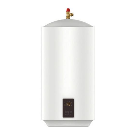
Thank you for purchasing a Powerflow series unvented electric water heater. The Powerflow is suitable for hand washing and dishwashing where a number of hot outlets are required such as kitchens, schools, restaurants, washrooms and offices. The Powerflow is the ideal solution for light industrial, commercial and light domestic hot water requirements. -
Page 3: Wall Mounting
Wall Mounting Plan your installation carefully in advance, allowing suitable space for installation and future access to all fittings as shown in diagram 1. Diagram 1 Temperature & Pressure Relief Valve Tundish Expansion Vessel POWERFLOW Pressure (Expansion) Relief Valve Balanced O Take Check Valve... - Page 4 Allow at least 500mm below and 200mm above the heater to facilitate future maintenance. To mount the heater, drill two holes for the supplied wall fixings and hang the heater onto them via the bracket at the rear. Plumbing connections Diagram 2...
- Page 5 Observe the flow direction arrows on fittings. It is important that the ordering of the fittings is correct as per the diagram 1 and 2. Do not remove the factory fitted pressure and temperature relief valve. Do not insert any other valves between the 3-way manifold and heater inlet since it may prevent the safe expansion and discharge of water during heating cycles.
- Page 6 Discharge pipe connections This product falls within the scope of Building Regulation G3 which stipulates certain conditions relating to the way any water discharge from relief valves is transported away. These conditions are designed to ensure that any discharge will not present a hazard to people or to property, and that any discharge is clearly visible so that the underlying cause is likely to be rectified promptly.
- Page 7 Diagram 3 Metal Discharge Pipe (D1) from Temperature Relief to Tundish Safety Device 600mm MAXIMUM Tundish 300mm MINIMUM Discharge Below Fixed Grating Fixed Grating Metal Discharge Pipe (D2) from Tundish with Continuous Fall Trapped Gully Sizing of D2 Copper Discharge pipe for common temperature relief valve outlet size Valve Minimum size of Minimum size of...
- Page 8 Electrical connections The heater is supplied pre-wired with the appropriate cable. The electrical installation should conform to the latest edition of the IEE wiring regulations. Electrical supply should be capable of isolation via a user-accessible double isolation switch rated for 13A supply. Diagram 4 Thermal Cutout...
- Page 9 3. Commissioning Visually confirm all plumbing and electrical connections look sound. Open any tap connected to the hot side of the unit and then turn on the incoming water supply to the heater. Allow the unit to fill until water flows smoothly from the open tap for around 1 minute to ensure the tank is purged of air and any plumbing related debris.
-
Page 10: Operation
4. Operation Turn on the heater by pressing the standby power button. On first power on, the heater will start in manual mode. To alter the target temperature of the heater, use the up/down buttons to cycle to the desired setting. The temperature is selectable between 30 C and 70 The target temperature will display for several seconds before the actual temperature of... -
Page 11: Maintenance
5. Maintenance Always disconnect the heater from the power supply before commencing any maintenance task. Servicing of electrical components should only be undertaken by competent individuals. Draining the unit To drain the unit, first isolate the power supply and close the service valve on the 3-way manifold. - Page 12 Remove the insulation from inside the heater. Locate and push the button in the centre of the thermal cut-out to reset the unit. If a cut-out event re-occurs, contact the technical team at Hyco on 01924 225200 for further advice.
- Page 13 De-scaling procedure Scale can build up over time and if unchecked will lead to impaired heating element performance and lifespan. For this reason, Hyco strongly recommends regular inspection of the inner tank and descaling as required. To access the inner tank, it is necessary to fully drain the tank and remove the heating element (see relevant sections in this manual).
- Page 14 Contact the Hyco technical support on 01924 225200 for further advise.
- Page 15 Expansion vessel maintenance The expansion vessel is supplied with a pre-charge of 3 bar, this pressure may be lost over time and should be checked periodically to keep the vessel functioning well and help prolong the lifespan of the tank. To check the pressure of the vessel, a reading should be taken while the unit is switched off and the content of the tank has been cooled.
-
Page 16: Specifications
6. Specifications MODEL PF30S PF50S PF80S PF100S Maximum supply pressure to 1.2 MPa reducing valve Power 3.0 kW Supply voltage/frequency 230V ~/50Hz Current Capacity (Litres) Operating pressure 0.3 MPa Maximum tank pressure 0.8 MPa Expansion vessel pre-charge 0.35 MPa Pressure reducing valve pre-set 0.3 MPa Pressure relief valve rating 0.6 MPA... - Page 17 Model 542mm 380mm 206mm 336mm 396mm 88mm 100mm 762mm 380mm 226mm 536mm 396mm 88mm 100mm 987mm 410mm 270mm 717mm 423mm 103mm 100mm 100L 1139mm 410mm 340mm 799mm 423mm 103mm 100mm...
-
Page 18: Troubleshooting
(see section 5 maintenance). If element ok then change PCB and thermistor contact hyco for further advice. No/limited water flow. Obstruction in Check flow from pressure pipework or the relief valve, if limited flow then heater inlet/outlet. - Page 19 Experience has shown that issues can often be resolved without the need to return or uninstall the product. 9. Approvals The Hyco Powerflow Smart range of water heaters complies with the LVD & EMC directives as required for the CE marking. The Hyco Powerflow Smart range of water heaters have been examined, tested and found, when correctly fitted, to comply with the requirements of the United Kingdom Water Regulations/Byelaws (Scotland).
- Page 20 In order to underline the duty to dispose of this equipment separately, the product is marked with a crossed out dustbin. Hyco Manufacturing Ltd Normandy Court Express Way...
Need help?
Do you have a question about the Powerflow Series and is the answer not in the manual?
Questions and answers