Advertisement
Available languages
Available languages
Quick Links
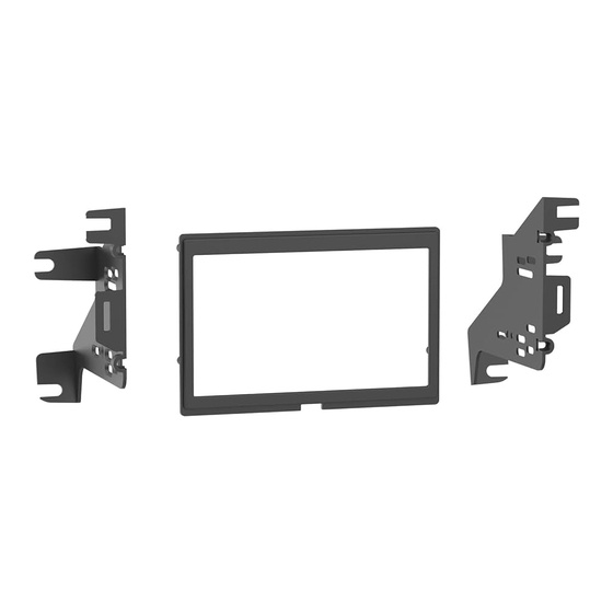
KIT COMPONENTS
• A) Radio trim panel • B) Radio brackets • C) #8 x 3/8" Phillips pan-head screws (4)
A
B
Metra. The World's Best Kits.
®
Mercedes Sprinter†
Visit
MetraOnline.com
for more detailed information about the product and up-to-date vehicle
specific applications
† Excluding models with a touchscreen radio
KIT FEATURES
• ISO DDIN radio provision
• Polished gloss black to match the factory finish
C
MetraOnline.com
2019-Up
© COPYRIGHT 2019 METRA ELECTRONICS CORPORATION
95-8731
I N S TA L L AT I O N I N S T R U C T I O N S
TABLE OF CONTENTS
Dash Disassembly ..................................................2
Kit Assembly ..........................................................3
WIRING & ANTENNA CONNECTIONS (sold separately)
Wiring Harness: Please visit metraonline.com
for wiring harness options
Antenna Adapter: Please visit metraonline.com
for antenna adapter options
TOOLS REQUIRED
• Panel removal tool • Phillips screwdriver
• Torx T-20 screwdriver
Attention!
With the key out of the ignition,
disconnect the negative battery terminal
before installing this product. Ensure that all
installation connections are secure before
cycling the ignition to test this product.
REV. 4/20/22 INST95-8731
Advertisement

Related Manuals for Metra Electronics 95-8731


Summary of Contents for Metra Electronics 95-8731
- Page 1 Ensure that all installation connections are secure before cycling the ignition to test this product. Metra. The World’s Best Kits. MetraOnline.com ® © COPYRIGHT 2019 METRA ELECTRONICS CORPORATION REV. 4/20/22 INST95-8731...
- Page 2 DASH DISASSEMBLY 1. Unclip and remove the radio trim panel. (Figure A) 2. Remove (4) Torx T-20 screws securing the radio and pocket assembly. Slide the assembly out, then unplug and remove. (Figure B) Continue to Kit Assembly (Figure A) (Figure B) 386.257.1187 MetraOnline.com...
- Page 3 KIT ASSEMBLY 1. Secure the radio brackets to the radio trim panel using (4) #8 x 3/8” Phillips pan-head screws provided. (Figure A) 2. Slide the radio into the bracket/panel assembly, then secure using screws supplied with the radio. (Figure B) 3.
- Page 4 Log onto www.installerinstitute.com or call 800-354-6782 for more information and take steps toward a better tomorrow. Metra recommends MECP certified technicians Metra. The World’s Best Kits. MetraOnline.com ® © COPYRIGHT 2019 METRA ELECTRONICS CORPORATION REV. 4/20/22 INST95-8731...
- Page 5 Al probar el equipo del mercado de accesorios, asegúrese de que todo el equipo de fábrica esté conectado antes de encender el llave de encendido. Metra. The World’s Best Kits. MetraOnline.com ® © COPYRIGHT 2019 METRA ELECTRONICS CORPORATION REV. 4/20/22 INST95-8731...
- Page 6 DESMONTAJE DEL TABLERO 1. Desenganche y quite el panel de la moldura para radio. (Figura A) 2. Quite (4) tornillos Torx T-20 que sujetan el ensamble de la cavidad y el radio. Deslice el ensamble para sacarlo. Después, desconéctelo y quítelo. (Figura B) Continúa con el ensamble del kit (Figura A)
- Page 7 ENSAMBLE DEL KIT 1. Fije los soportes del radio al panel de moldura para radio con (4) tornillos Phillips de cabeza troncónica #8 x 3/8” incluidos. (Figura A) 2. Deslice el radio dentro del ensamble del panel/soporte. Después, fíjelo con los tornillos incluidos con el radio.
- Page 8 Log onto www.installerinstitute.com or call 800-354-6782 for more information and take steps toward a better tomorrow. Metra recomienda MECP técnicos certificados Metra. The World’s Best Kits. MetraOnline.com ® © COPYRIGHT 2019 METRA ELECTRONICS CORPORATION REV. 4/20/22 INST95-8731...
Need help?
Do you have a question about the 95-8731 and is the answer not in the manual?
Questions and answers