Advertisement
Quick Links
Advertisement

Subscribe to Our Youtube Channel
Summary of Contents for Aeros ANT-E
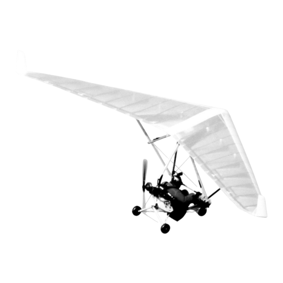
- Page 1 AEROS NANOLIGHT TRIKE ANT-E QUICK GUIDE Wing: Combat-T, Discus-T, Fox-13TL, Fox-T Electric power plant Manufactured by: AEROS Ltd Tel: (380 44) 455 41 20 Post-Volynskaya St.5 Fax: (380 44) 455 41 16 Kiev 03061 E-mail: info@aeros.com.ua UKRAINE http://www.aeros.com.ua February 2018...
-
Page 2: Important Notices
It was prepared as a guide to pilots, before their first flight with ANT-E, in order to do it in proper and safe way. This Quick Guide should only be used as a refresh document prior to flying and not as a substitute for the full manual. - Page 3 1. Trike Assembly Procedure The trike comes in two bags – the trike and the motor with controller. The package includes also the propeller, the upper pylon and the front brace tube. 1.1 Unzip the bag with the trike. 1.2 Open the front lower beam with the front wheel. Be careful not to drop the SDI (Smart Drive Interface) / ADI (Advanced Drive Interface) unit.
- Page 4 Make sure the both legs of the landing gear are locked: 1.4 Open the bag with the motor. Mount the motor on the trike by installing two bolts: upper one and lower one. Install the bolts, install the butterfly nuts and secure them with safety rings. Tighten the bolts with their arms firmly.
- Page 5 1.5 Connect the COM port to the controller and tighten it firmly with the screws. 1.6 Connect battery management system cables to the batteries. Connect power cables. Tie the cables together with bundle ties as shown on the photo. 1.7 Install the main upper pylon and fix it with the lower bolt and butterfly nuts and secure with safety rings. Do not tighten the bolt for now.
-
Page 6: Starting The Engine
1.9 Install the propeller and secure it with a pin and a safety ring. Now your trike is ready for attaching the wing. Refer to the ANT Owner/Service Manual for more information. 2. Starting the engine 2.1 Press and hold for 1 second the green button (aftermost button) on the battery unit (aftermost battery) for to switch on the battery management system. - Page 7 The motor can be deactivated at any time by pressing the start button quickly on the ADI (SDI) unit. WARNING: Keep in mind that while the continuous beep sounds, the engine is active and can be started. This mode is equivalent to the idle mode of the conventional piston engine.
-
Page 8: Troubleshooting
WARNING: It is prohibited to use the reverse button in flight - this can cause a dangerous loss of speed. 3. ENGINE CONTROLLER PI300 FUNCTIONALITY The accidental start of the engine is prevented by the controller. The signal to the controller for the possibility of starting is the "minimum"... - Page 9 a) Connect the charger to each battery individually and start the charging process by turning on only one of the batteries by pressing the On button. b) Connect a single charger to the master battery and start it with the On button. After the charging process is started on the master battery, start the connection to the engine controller by pressing again the On button on the master battery for 2 seconds.
- Page 10 green LED on the battery blinks charging process will only be unlocked after reaching the set temperature threshold (default 45 ° C) Check the connector, if necessary, use a different connector. The charging connector is not powered The charger is malfunctioned Replace the charger 6.
- Page 11 The table below describes possible SDI error codes and possible system response to them. Error Description System response code Low battery voltage; Unlocking the controller is deactivated. The drive stops. The 40.0 V voltage limit A warning tone sounds (intermittent 4-second sound) exceedance Excess inverter temperature;...


Need help?
Do you have a question about the ANT-E and is the answer not in the manual?
Questions and answers